


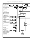
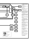

TM-353 Page 24 Syncrowave 250
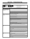
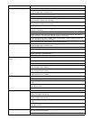
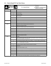
Trouble Remedy
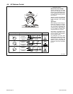
No high frequency at spark gaps G.
Check position of High Frequency switch S2 (see Section 4-11).
Place Output (Contactor) switch S3 in Remote position and be sure remote control is connected to
Remote receptacle RC1 (see Section 3-8).
Check circuit breaker CB1, and reset if open (see Section 7-2).
Check fuse F1 in rectifier SR2 circuit, and replace if necessary.
Check coil voltage and connections of contactor control relay CR1. Check continuity of coil and con-
dition of contacts. Replace CR1 if necessary.
Check coil voltage and connections of contactor control relay CR5. Check continuity of coil and con-
dition of contacts. Replace CR5 if necessary.
Check spark gaps G, and readjust if necessary (see Section 7-4).
Check resistance and connections of High Frequency Intensity control R13; R13 is 1.5 ohms ±10%.
Replace R1 if necessary.
Check capacitor C4 for a short or open, and check for proper connections. Replace C4 if necessary.
Check transformer T2 for signs of winding failure. Check continuity across windings, and check for
proper connections. Check secondary voltages. Replace T2 if necessary.
Check coupling coil T3 for signs of winding failure. Check continuity across windings, and check for
proper connections. Replace T3 if necessary.
Check control board PC1 and connections, and replace if necessary.
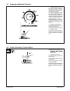
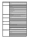
No preflow time (optional). Place Output (Contactor) switch S3 in Remote position and be sure remote control is connected to
Remote receptacle RC1 (see Section 3-8).
Check position of Preflow Time control R12.
Check continuity of Preflow Time switch S9. Check condition of contacts. Repair or replace S9 if nec-
essary.
Remove jumper link 1 on terminal strip 1T.
Check optional preflow timer board TD3, and replace if necessary.
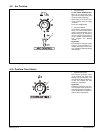
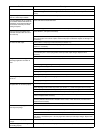
Optional spot timer relay TD2 does not
time out.
Place Spot Time switch S8 in the On position.
Remove jumper link 2 from terminal strip 1T.
Place Spot Time control R10 in desired position.
Check coil voltage and connections of spot timer relay TD2. Check continuity of coil and condition of
contacts. Replace TD2 if necessary.
Check coil voltage and connections of control relay CR3. Check continuity of coil and condition of
contacts. Replace CR3 if necessary.
Check coil voltage and connections of control relay CR1. Check continuity of coil and condition of
contacts. Replace CR1 if necessary.
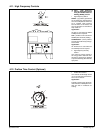
Postflow timer does not time out. Check position of Postflow Time control setting (see Section 4-10).
Check Control relay CR5 contacts 2 and 5 for proper operation. Replace CR5 if necessary.
Check coil voltage and connections of gas valve GS1. Check continuity of coils. Replace GS1 if nec-
essary.
Check input voltage and connections to Postflow timer board TD1. Check continuity of contacts. Re-
place TD1 if necessary.
Check control board PC1 and connections, and replace if necessary.
No postflow time. Check position of Postflow Time control setting (see Section 4-10).
Place Output(Contactor) switch S3 in the Remote position, and connect a remote control to recep-
tacle RC1 according to Section 3-8.
Check coil voltage and connections of control relay CR5. Check continuity of coil and condition of
contacts. Replace CR5 if necessary.
Check coil voltage and connections of gas valve GS1. Check continuity of coils. Replace GS1 if nec-
essary.
Check input voltage and connections to Postflow timer board TD1. Check continuity of contacts. Re-
place TD1 if necessary.
Check control board PC1 and connections, and replace if necessary.
No gas flow. Place Output(Contactor) switch S3 in the Remote position, and connect a remote control to recep-
tacle RC1 according to Section 3-8.
Check circuit breaker CB1, and reset if open (see Section 7-2).