


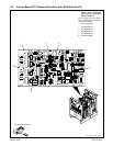
TM-353 Page 27Syncrowave 250
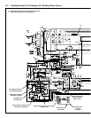
SC-188 161
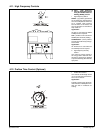
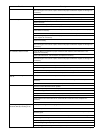
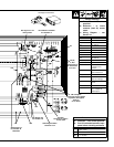
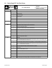
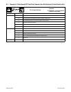
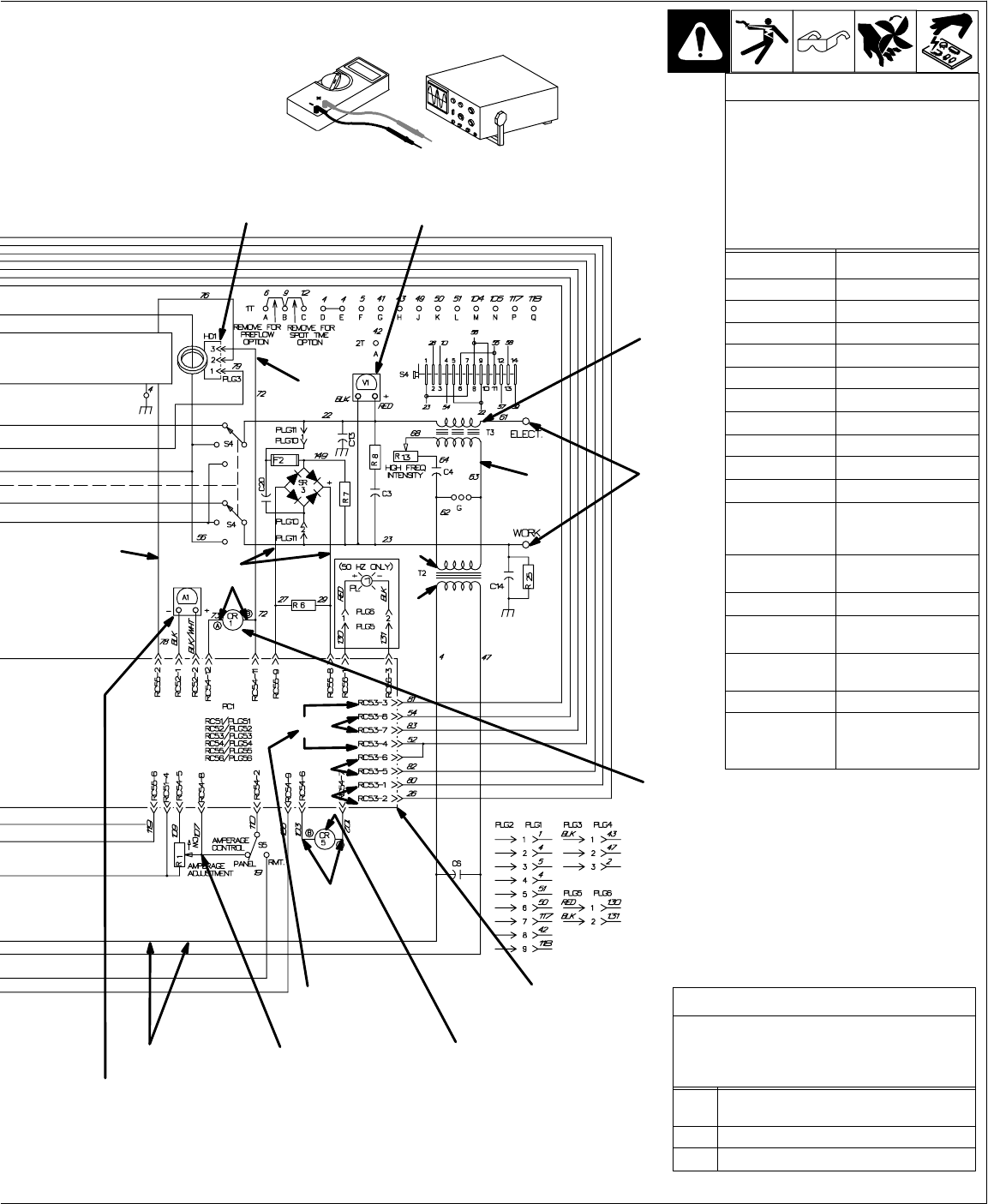
Test Equipment Needed:
V24
V22
V21
R3
R2
V20
A
A
A
A
R1
V25
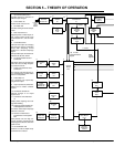
Resistance Values
a) Tolerance – ±10% unless specified
b) Turn Off unit and disconnect input
power before checking resistance
R1 All values for T1, Z1, and T3 are less
than 1 ohm
R2 5.3 ohms
R3 6.1 K ohms
Voltage Readings
a) Tolerance – ±10% unless
specified
b) Reference – to circuit
common (lead 42) unless
noted
c) Wiring Diagram – see
Section 10
V1 230 volts ac
V2 77 volts ac
V3 82.5 volts ac
V4 57 volts ac
V5, V6 115 volts ac
V7 24 volts ac
V8, V9 18 volts ac
V10 10 volts ac
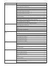
V11 80 volts dc
V12. V13, V14 115 volts ac
V15, V16, V17 24 volts ac
V18 115 volts ac with S2
in Start or Con-
tinuous
V19 0 to +10 volts dc
with contactor on
V20, V21 24 volts dc
V22 0-80 volts dc (rec-
tified arc voltage)
V23 maximum 80 volts
ac/dc
V24 24 volts dc
V25 16.5 millivolts dc
per 1 ampere of
weld output
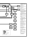
CR1 energizes
when open-circuit voltage
is present; denergizes
when an
arc is struck
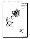
See Figure 10-1 for
HD1 location
No calibration available
for voltmeter V1
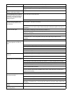
R1
V23, B,
C, D, E
See Section 6-3
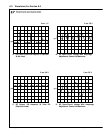
for waveforms
B, C, D, E
See also
Sections 6-4 and 6-5
for PC1 data
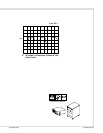
CR5 energizes when
contactor is on
See Section 6-8
for ammeter A1
calibration
V19
V18
See Section 6-3
for waveform A