


TM-353 Page 23Syncrowave 250
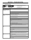
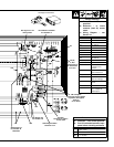
Trouble Remedy
Check SCRs in main rectifier SR1, and replace if necessary. If any SCRs are replaced, Check capac-
itors C7 through C10 for a short or open, and check for proper connections. Replace C7 through C10
if necessary.
Check control board PC1 and connections, and replace if necessary.
Check connections to line filter FL1. Check input to PC1. Replace FL1 if necessary.
Erratic weld output.
Check for poor or improper input or output connections. See Sections 3-11 and 3-8.
Replace electrode.
Check torch assembly, and replace if necessary.
Check fuse F2 in rectifier SR3 circuit, and replace if necessary.
If Amperage Control switch S5 is in the Remote position check, repair, or replace remote amperage
control device if necessary.
Check connections for continuity to shunt device on units with Serial No. prior to KB110695.
Check Amperage Adjustment control R1 for proper connections and resistance; R1 is 1000 ohms
±10%. Replace R1 if necessary.
Check bypass capacitors C13, C14, C16, C17, C18, and C19 for broken leads, shorts, and leakage.
Replace if necessary.
Check SCRs in main rectifier SR1, and replace if necessary. If any SCRs are replaced, Check capac-
itors C7 through C10 for a short or open, and check for proper connections. Replace C7 through C10
if necessary.
Check control board PC1 and connections, and replace if necessary.
No or limited ac balance control. Check AC Balance control R3 for proper connections and resistance; R3 is 5000 ohms ±10%.
Replace R3 if necessary.
Check control board PC1 and connections, and replace if necessary.
Check SCRs in main rectifier SR1, and replace if necessary. If any SCRs are replaced, Check capac-
itors C7 through C10 for a short or open, and check for proper connections. Replace C7 through C10
if necessary.
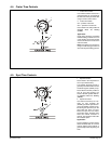
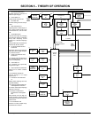
No crater fill time. Check position of Crater switch S7 (see Section 4-4).
Check position of Crater control R11 (see Section 4-4).
Be sure arc voltage is below 24 volts (see Section 3-2. Volt-Ampere Curves).
Check position of Amperage Control switch S5, S5 must be in Panel position (see Section 4-7).
Check control board PC1 and connections, and replace if necessary.
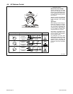
Crater fill time too long or does not
time out.
Check position of Crater control R11 (see Section 4-4).
Check resistance and connections of Crater control R11; R11 is 5 meg ohms ±10%. Replace R11 if
necessary.
Check control board PC1 and connections, and replace if necessary.
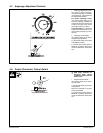
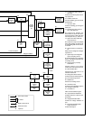
No arc control.
Place Arc Control switch S6 in the On position.
Place High Frequency switch S2 in the Off position.
Be sure arc voltage is below 24 volts (see Section 3-2. Volt-Ampere Curves).
Check position of Arc Control R2 (see Section 4-9).
Check fuse F1 in rectifier SR3 circuit, and replace if necessary.
Check resistance and connections of Arc control R2; R2 is 1000 ohms ±10%. Replace R1 if
necessary.
Check control board PC1 and connections, and replace if necessary.
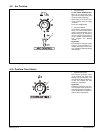
Lack of high frequency at tungsten
electrode; difficulty in starting an arc.
Use proper size tungsten for welding application.
Use shortest possible cables (see Section 3-7).
Check cables and torch for cracked or deteriorated insulation or bad connections. Repair or replace
necessary parts.
Be sure to disconnect SMAW electrode cable from weld output terminal when GTAW welding.
Decrease gas flow setting.
Use properly prepared tungsten.
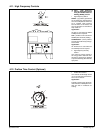
Increase setting of High Frequency Intensity control R13 (see Section 4-11).
Check spark gaps G, and readjust if necessary (see 7-4).