


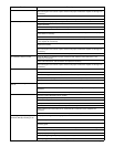
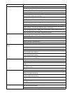
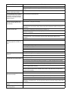
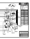
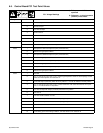
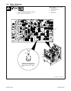
TM-353 Page 31Syncrowave 250
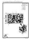
6-5. Control Board PC1 Test Point Values
PC1 Voltage Readings
a) Tolerance –
±10% unless
specified
b) Reference – to circuit common
(lead 42) unless noted
Receptacle Pin Value
RC51 1 18 volts ac input
2 18 volts ac input
3 +10 volts dc output
4 Circuit common
5 Not used
6 Not used
RC52 1 Circuit common
2 +1 millivolt dc per 3 ampere of weld output
RC53 1 Gate pulse for SCR1 with respect to pin 2 (see Section 6-3)
2 Reference for gate pulse to SCR1
3 Gate pulse for SCR3 with respect to pin 4 (see Section 6-3)
4 Reference for gate pulse to SCR3
5 Gate pulse for SCR2 with respect to pin 6 (see Section 6-3)
6 Reference for gate pulse to SCR2
7 Gate pulse for SCR4 with respect to pin 8 (see Section 6-3)
8 Reference for gate pulse to SCR4
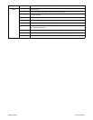
RC54 1 Not used
2 0 to +10 volts dc input from min. to max. of Amperage Adjustment control R1 with Amperage Control
switch S5 in Panel position, and contactor on
3 0 volts with Output (Contactor) switch S3 in On position or +7.8 volts dc with S3 in Remote position
4 0 to +10 volts dc input from min. to max. of Crater Control R11 with Crater Fill switch S7 in On posi-
tion, or +10 volts dc with S7 in Off position
5 +10 volts dc output with Output (Contactor) switch S3 in On position
6 –24 volts dc
7 –24 volts dc with contactor on or off
8 0 to +10 volts dc input from min. to max. of Amperage Adjustment control R1 with contactor on
9 0 to +10 volts dc input from min. to max. of Amperage Adjustment control R1 with contactor on
10 Circuit common
11 +24 volts dc
12 0 volts during open-circuit voltage condition; +24 volts with arc on or contactor off