


Serial port 127
Models 2603, 2621, and 2635 Getting Started Guide D • IPLink Physical Connectors
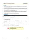
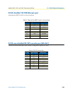
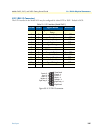
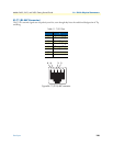
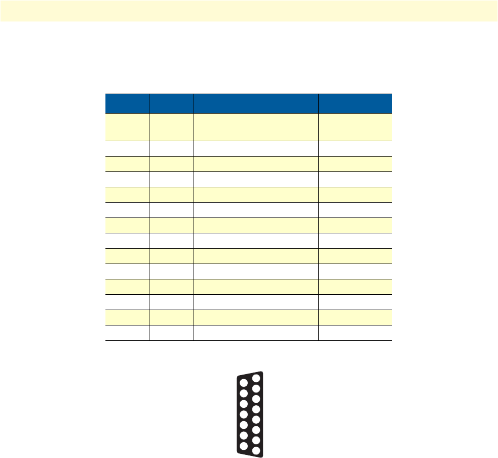
X.21 (DB-15 Connector)
The X.21 interface in the Model 2621 may be configured for either DTE or DCE. Default is DCE.
Figure 85. X.21 DB-15 connector
Table 10. X.21 Interface (Model 2621)
Pin No. Circuit Signal Name Direction
1 G Signal Ground or Common
Return
-
2 T Transmit (Data)-a from DTE
3 C Control-a from DTE
4 R Receive (Data)-a to DTE
5 I Indication-a to DTE
6 S Signal Timing-a to DTE
7 - - -
8 Ga DTE Common Return -
9 T Transmit (Data)-a from DTE
10 C Control-b from DTE
11 R Receive (Data)-b to DTE
12 I Indication-b to DTE
13 S Signal Timing-b to DTE
14, 15 - - -
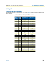
1 Frame Ground
2 Transmit – A
3 Control – A
4 Receive – A
5 Indication – A
6 Signal Timing – A
7
8 Signal Ground
9
10
11
12
13
14
15
Transmit – B
Control – B
Receive – B
Indication – B
Signal Timng – B