


IPLink Series High Speed Routers overview 21
Models 2603, 2621, and 2635 Getting Started Guide 1 • General Information
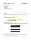
Console port
Located on the front panel, the unshielded RJ-45 RS-232 console DCE port (EIA-561) with the pin-out listed
in the following table
:
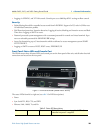
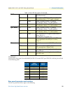
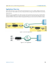
Rear panel connectors and switches
On the rear panel from left to right are the following:
T1/E1 Link Green Solid green: connected
Off: disconnected
LOS Red On: indicates a T1/E1 loss-of-frame condition. It
also indicates that no T1/E1 signal is detected.
TD Green Green: indicates a binary ‘0’ condition
off: indicates a binary ‘1’or idle condition
RD Green Green: indicates a binary ‘0’condition
off: indicates a binary ‘1’ or idle condition
Sync Serial TD Green Green: indicates a binary ‘0’ condition
off: indicates a binary ‘1’or idle condition
RD Green Green: indicates a binary ‘0’condition
off: indicates a binary ‘1’ or idle condition
CTS Green ON: indicates the CTS signal from the router is
active, binary ‘1’
off: indicates CTS is binary ‘0’
DTR Green ON: indicates the DTR signal from the DTE
device attached to the serial port is active,
binary ‘1’
Ethernet Link Green ON: indicates an active 10/100 Base-T connec-
tion
100M Green ON: connected to a 100BaseT LAN
Off: connected to a 10BaseT LAN
Tx Green Flashing: when transmitting data from the router
to the Ethernet
Rx Green Flashing: when transmitting data from the Ether-
net to the router.
Pin No.
Signal
Direction
Signal
Name
1 Out DSR
2 Out CD
3 In DTR
4 — Signal Ground
5 Out RD
6 In TD
7 Out CTS
8 In RTS
Table 2. Status LED descriptions (Continued)