


WAN Service Configuration 58
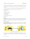
Models 2603, 2621, and 2635 Getting Started Guide 6 • WAN Services
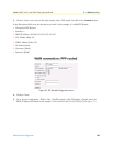
• Username: [blank]
• Password: [blank]
Click on the Create button.
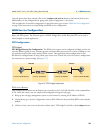
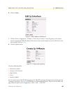
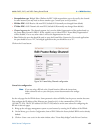
4. Go to Services Configuration > WAN > Edit... (for PPP routed) > Edit ‘IP Interface’ > Ipaddr: [enter the
WAN IP Address and Mask, in this example = 192.168.164.3 and 255.255.255.255].
5. Click on Create.
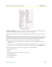
6. Go to Configuration Menu > Configuration > IP Routes > Click on Create new Ip V4 Route.
7. Create the gateway to the remote IPLink by entering the WAN IP address of the remote IPLink, in this
example, enter 192.168.164.2 in the Gateway field
8. Click OK.
The other fields should be:
• Destination:0.0.0.0
• Gateway:192.168.164.2
• Mask:0.0.0.0
• Cost 1
• Interface: [blank]
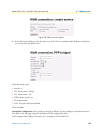
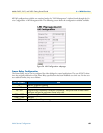
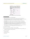
You can see the status of the PPP link by going to the ‘Edit PPP’ web page and paging down until you see the
“Summary” description. To get to the ‘Edit PPP’ web page, follow this path: Services Configuration > WAN >
Edit... > Edit ‘PPP’
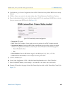
LMI Management (Frame Relay links)
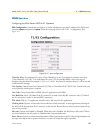
LMI Configuration
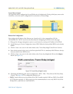
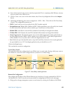
Frame Relay Local Management Interface. The Frame Relay Local Management Interface (LMI) is a mech-
anism that two separate frame relay systems can use to communicate the status of the interface. The LMI inter-
face allows dynamic updates on the status of the DLCI connections and the congestion state of the network.
The IPLink implements all three versions of LMI available within the frame relay network. These are defined
in table 3:
Note LMI uses DLCI 0, but ANSI/CCITT has also reserved 1–15. Best practice
(per the recommendation) is to use only DLCIs 16–991 for FR data PVCs,
and DLCIs 0–15 for LMI PVCs.
Table 3. LMI Implementation on the IPLink
Protocol Specification Options Available
LMI Frame Relay Forum Implementation Agreement
(IA) FRF.1 superseded by FRF.1.1
User Side
Annex D ANSI T1.617 User Side
Annex A ITU Q.933 referenced in FRF.1.1 User Side