


Hardware installation 34
Models 2603, 2621, and 2635 Getting Started Guide 3 • Initial Configuration
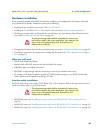
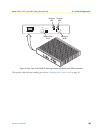
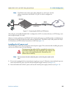
Note The IPLink comes with a V.35 cable configured as a tail-circuit. Use this
cable to interconnect the IPLink’s V.35 port to a device configured as
a DCE.
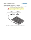
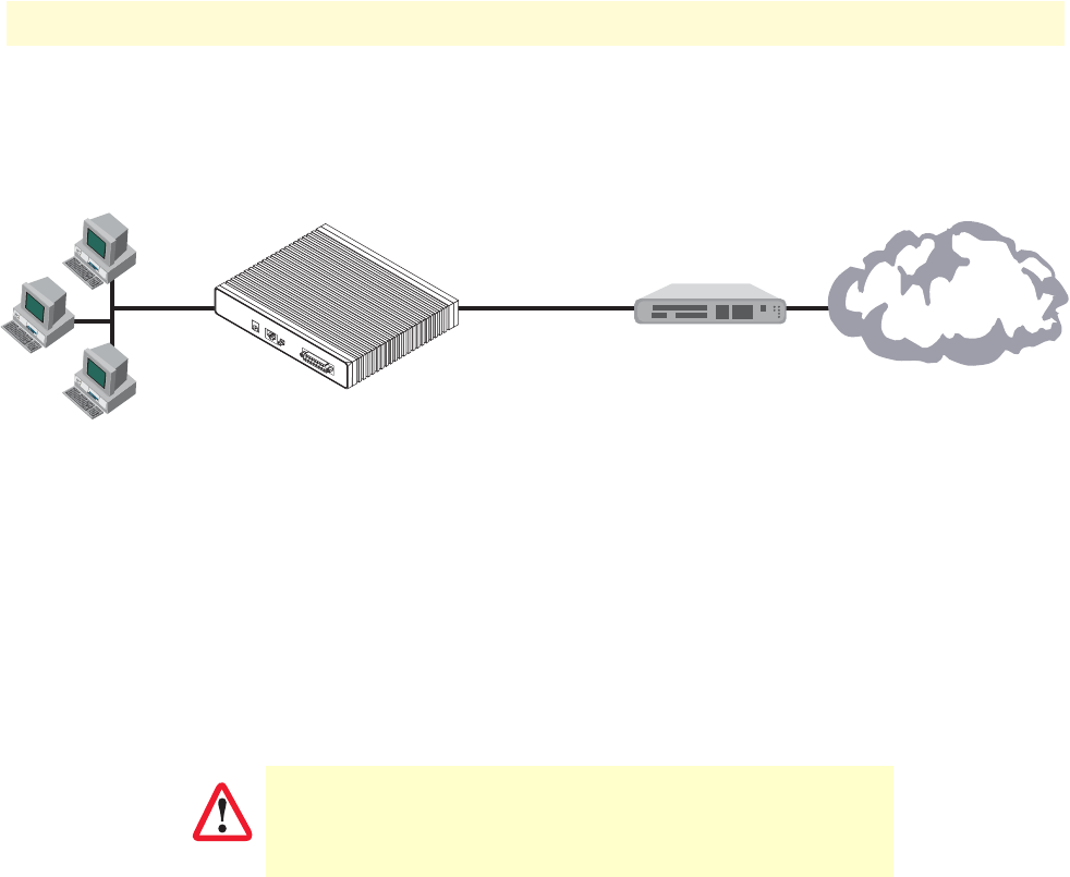
Figure 11. Connecting the 2635 to a DCE device
The serial port on the IPLink Model 2635 is configured as a DCE, it connects directly to a DTE using a stan-
dard straight-through V.35 cable.
However, in many applications, the IPLink’s V.35 interface will connect to a DCE (modem or multiplexer), in
this situation use the special cable provided with your Model 2635. This DB-25/M35 cable presents the 2635’s
V.35 interface as a DTE for direct connection to a DCE (see figure 11).
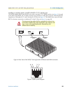
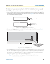
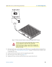
Installing the AC power cord
The IPLink router comes with an internal or external power supply. This section describes installing the power
cord into the IPLink router. Do the following:
Note Do not connect the other end of the power cord to the power outlet at this
time.
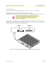
1. If your unit is equipped with an internal power supply, go to step 2. Otherwise, insert the barrel type con-
nector end of the AC power cord into the external power supply connector (see figure 12).
2. Insert the female end of the AC power cord into the internal power supply connector (see figure 12).
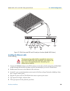
The interconnecting cables shall be acceptable for external use
and shall be rated for the proper application with respect to volt-
age, current, anticipated temperature, flammability, and
mechanical serviceability.
2635 IPLink
Use cable provided
with 2635 IPLink
V.35
Modem
DCE
MDI-X
Crossover
10/100
Ethernet
WAN
X.21 Interface
Power
CAUTION