


2000 Sep 06 10
Philips Semiconductors
Magnetoresistive sensors for
magnetic field measurement
General
Using magnetoresistive sensors
The excellent properties of the KMZ magnetoresistive
sensors, including their high sensitivity, low and stable
offset, wide operating temperature and frequency ranges
and ruggedness, make them highly suitable for use in a
wide range of automotive, industrial and other
applications. These are looked at in more detail in other
chapters in this book; some general practical points about
using MR sensors are briefly described below.
ANALOG APPLICATION CIRCUITRY
In many magnetoresistive sensor applications where
analog signals are measured (in measuring angular
position, linear position or current measurement, for
example), a good application circuit should allow for
sensor offset and sensitivity adjustment. Also, as the
sensitivity of many magnetic field sensors has a drift with
temperature, this also needs compensation. A basic circuit
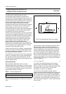
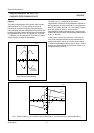
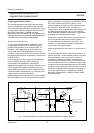
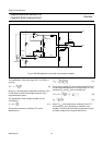
is shown in Fig.11.
In the first stage, the sensor signal is pre-amplified and
offset is adjusted. After temperature effects are
compensated, final amplification and sensitivity
adjustment takes place in the last stage. This basic circuit
can be extended with additional components to meet
specific EMC requirements or can be modified to obtain
customized output characteristics (e.g. a different output
voltage range or a current output signal).
Philips magnetoresistive sensors have a linear sensitivity
drift with temperature and so a temperature sensor with
linear characteristics is required for compensation. Philips
KTY series are well suited for this purpose, as their
positive Temperature Coefficient (TC) matches well with
the negative TC of the MR sensor. The degree of
compensation can be controlled with the two resistors R7
and R8 and special op-amps, with very low offset and
temperature drift, should be used to ensure compensation
is constant over large temperature ranges.
Please refer to part 2 of this book for more information on
the KTY temperature sensors; see also the Section
“Further information for advanced users” later in this
chapter for a more detailed description of temperature
compensation using these sensors.
USING MAGNETORESISTIVE SENSORS WITH A COMPENSATION
COIL
For general magnetic field or current measurements it is
useful to apply the ‘null-field’ method, in which a magnetic
field (generated by a current carrying coil), equal in
magnitude but opposite in direction, is applied to the
sensor. Using this ‘feedback’ method, the current through
the coil is a direct measure of the unknown magnetic field
amplitude and it has the advantagethat the sensor is being
operated at its zero point, where inaccuracies as result of
tolerances, temperature drift and slight non-linearities in
the sensor characteristics are insignificant. A detailed
discussion of this method is covered in Chapter “Weak
field measurement”.
Fig.11 Basic application circuit with temperature compensation and offset adjustment.
handbook, full pagewidth
MBH687
3
4
1
2
KMZ10B
offset
adjustment
R3
22 kΩ
R4
14 kΩ
R2
500 kΩ
R1
100 kΩ
2
3
4
1
8
R6
KTY82-210
TLC2272
R5
140 kΩ
R7
2.4 kΩ
R8
2.4 kΩ
R9
33 kΩ
R10
33 kΩ
6
5
7
IC1
R11
22 kΩ
R12
150 kΩ
sensitivity
adjustment
C1
10 nF
V = 5 V
S
V = 0.2 V to 4.8 V
O
(with resistive load
greater than 10 kΩ)
op-amp
op-amp