


2000 Sep 06 13
Philips Semiconductors
Magnetoresistive sensors for
magnetic field measurement
General
The following general recommendations for operating the
KMZ10 can be applied:
• To ensure stable operation, avoid operating the sensor
in an environment where it is likely to be subjected to
negative external fields (‘−H
x
’). Preferably, apply a
positive auxiliary field (‘H
x
’) of sufficient magnitude to
prevent any likelihood of flipping within he intended
operating range (i.e. the range of ‘H
y
’).
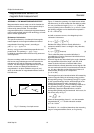
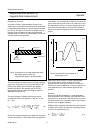
• Before using the sensor for the firsttime, apply a positive
auxiliary field of at least 3 kA/m; this will effectively erase
the sensor’s magnetic ‘history’ and will ensure that no
residual hysteresis remains (refer to Fig.6).
• Use the minimum auxiliary field that will ensure stable
operation, because the larger the auxiliary field, the
lower the sensitivity, but the actual value will depend on
the value of H
d
. For the KMZ10B sensor, a minimum
auxiliary field of approximately 1 kA/m is recommended;
to guarantee stable operation for all values of H
d
, the
sensor should be operated in an auxiliary field of 3 kA/m.
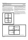
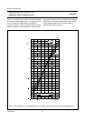
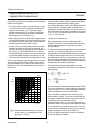
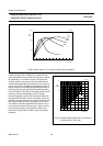
These recommendations (particularly the first one) define
a kind of Safe Operating ARea (SOAR) for the sensors.
This is illustrated in Fig.15, which is an example (for the
KMZ10B sensor) of the SOAR graphs to be found in our
data sheets.
The greater the auxiliary field, the greater the disturbing
field that can be tolerated before flipping occurs.
For auxiliary fields above 3 kA/m, the SOAR graph shows
that the sensor is completely stable, regardless of the
magnitude of the disturbing field. It can also be seen from
this graph that the SOAR can be extended for low values
of ‘H
y
’. In Fig.15, (for the KMZ10B sensor), the extension
for H
y
< 1 kA/m is shown.
TEMPERATURE COMPENSATION
With magnetoresistive sensors, temperature drift is
negative. Two circuits manufactured in SMD-technology
which include temperature compensation are briefly
described below.
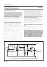
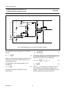
The first circuit is the basic application circuit already given
(see Fig.11). It provides average (sensor-to-sensor)
compensation of sensitivity driftwith temperature using the
KTY82-210 silicon temperature sensor. It also includes
offset adjustment (via R1); gain adjustment is performed
with a second op-amp stage. The temperature sensor is
part of the amplifier’sfeedback loop and thus increases the
amplification with increasing temperature.
The temperature dependant amplification A and the
temperature coefficient TC
A
of the first op-amp stage are
approximately:
for R
8
=R
7
for R
8
=R
7
R
T
is the temperature dependent resistance of the KTY82.
The values are taken for a certain reference temperature.
This is usually 25 °C, but in other applications a different
reference temperature may be more suitable.
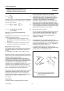
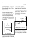
Figure 16 shows an example with a commonly-used
instrumentation amplifier. The circuit can be divided into
two stages: a differential amplifier stage that produces a
symmetrical output signal derived from the
magnetoresistive sensor, and an output stage that also
provides a reference to ground for the amplification stage.
To compensate for the negative sensor drift, as with the
above circuit the amplification is again given an equal but
positive temperature coefficient, by means of a
KTY81-110 silicon temperature sensor in the feedback
loop of the differential amplifier.
Fig.15 SOAR of a KMZ10B sensor as a function of
auxiliary field ‘H
x
’ and disturbing field ‘H
d
’
opposing ‘H
x
’ (area I).
handbook, halfpage
012 4
12
0
4
8
MLC133
3
H
d
(kA/m)
H (kA/m)
x
I
II
SOAR
A
R
5
R
3
-------
= 1
2R
T
R
7
-----------
+
TC
A
TC
KTY
1
R
7
2R
T
-----------
+
---------------------
=