


2000 Sep 06 12
Philips Semiconductors
Magnetoresistive sensors for
magnetic field measurement
General
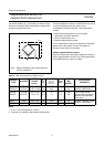
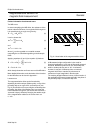
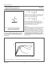
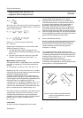
For sensors using Barber poles arranged at an angle of
+45° to the strip axis, the following expression for the
sensor characteristic can be derived (see Appendix 1 on
the MR effect):
(7)
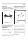
The equation is linear where H/H
o
= 0, as shown in Fig.7.
Likewise, for sensors using Barber poles arranged at an
angle of −45°, the equation derives to:
(8)
This is the mirror image of the characteristic in Fig.7.
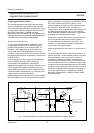
Hence using a Wheatstone bridge configuration ensures
the any bridge imbalance is a linear function of the
amplitude of the external magnetic field.
F
LIPPING
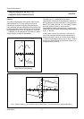
As described in the body of the chapter, Fig.7 shows that
flipping is not instantaneous and it also illustrates the
hysteresis effect exhibited by the sensor. This figure and
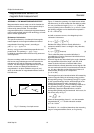
Fig.14 also shows that the sensitivity of the sensor falls
with increasing ‘H
x
’. Again, this is to be expected since the
moment imposed on the magnetization by ‘H
x
’ directly
opposes that imposed by ‘H
y
’, thereby reducing the degree
of bridge imbalance and hence the output signal for a
given value of ‘H
y
’.
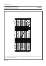
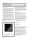
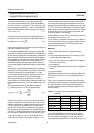
Fig.13 The resistance of the permalloy as a
function of the external field H after
linearization (compare with Fig.6).
handbook, halfpage
MLC126
H
R
RR
O
∆R
O
2
------------
∆ R
O
H
H
O
--------
1
H
2
H
O
2
--------
–++=
RR
O
∆R
O
2
------------
∆ R
O
H
H
O
--------
1
H
2
H
0
2
-------
––+=
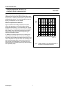
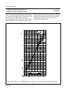
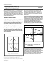
Fig.14 Sensor output ‘V
o
’ as a function of the transverse field ‘H
y
’ for several values of auxiliary field ‘H
x
’.
handbook, full pagewidth
MLC132
0
24681012
O
(mV)
H (kA/m)
y
H =
4 kA/m
x
2 kA/m
1 kA/m
0
V
100
150
50