


2000 Sep 06 18
Philips Semiconductors
Magnetoresistive sensors for
magnetic field measurement
General
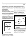
This definition relates DU to a unit operating voltage.
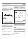
The highest (H
G
) and lowest (H
min
) fields detectable by
the sensor are also of significance. The measuring range
H
G
is restricted by non-linearity - if this is assumed at 5%,
an approximate value for barber-pole sensors is given by:
(11)
From this and equation (9) for signal voltage (U
BP
) for a
barber-pole sensor, the following simple relationship can
be obtained: (12)
Other sensor types have a narrower range of linearity and
therefore a smaller useful signal.
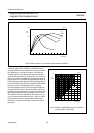
The lowest detectable field H
min
is limited by offset, drift
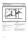
and noise. The offset is nearly cancelled in a bridge circuit
and the remaining imbalance is minimized by symmetrical
design and offset trimming, with thermal noise negligible in
most applications (see section on sensor layout). Proper
film deposition and, if necessary, the introduction of a
stabilization field will eliminate magnetization switching
due to domain splitting andthe introduction of ‘Barkhausen
noise’.
Sensitivity S
0
is essentially determined by the sum of the
anisotropy (H
k
), demagnetization (H
d
) and bias (H
x
) fields.
The highest sensitivity is achievable with H
x
= 0 and
H
d
«H
k
, although in this case S
0
depends purely on H
k
which is less stable than H
d
. For a permalloy with a
thickness greater than or equal to 20 µm, a width in
excess of 60 µm is required which, although possible, has
the drawback of producing a very low resistance per unit
area.
The maximum theoretical S
0
with this permalloy (at
H
k
= 250 A/m and ∆ρ/ρ = 2.5%) is approximately:
(13)
For the same reasons, sensors with reduced sensitivity
should be realized with increased H
d
, which can be esti-
mated at a maximum for a barber-pole sensor at 40 kA/m.
A further reduction in sensitivity and a corresponding
growth in the linearity range is attained using a biasing
field. A magnetic shunt parallel to the magnetoresistor or
only having a small field component in the sensitive direc-
tion can also be employed with very high field strengths.
A high signal voltage U
x
can only be produced with a
sensor that can tolerate a high supply voltage U
o
. This
requires a high sensor resistance R with a large area A,
since there are limits for power dissipation and current
density. The current density in permalloy may be very high
(j > 10
6
A/cm
2
in passivation layers), but there are weak
points at the current reversal in the meander (see section
on sensor layout) and in the barber-pole material, with
five-fold increased current density.
A high resistance sensor with U
0
= 25 V and a maximum
S
0
results in a value of 2.5 x 10
-3
(A/m)
-1
for Su or, converted to flux density, S
T
= 2000 V/T.
This value is several orders of magnitude higher than for a
normal Hall effect sensor, but is valid only for a much
narrower measuring range.
Materials
There are five major criteria for a magnetoresistive
material:
• Large magnetoresistive effect Dr/r (resulting in a high
signal to operating voltage ratio)
• Large specific resistance r (to achieve high resistance
value over a small area)
• Low anisotropy
• Zero magnetostriction (to avoid influence of mechanical
stress)
• Long-term stability.
Appropriate materials are binary and ternary alloys of Ni,
Fe and Co, of which NiFe (81/19) is probably the most
common.
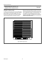
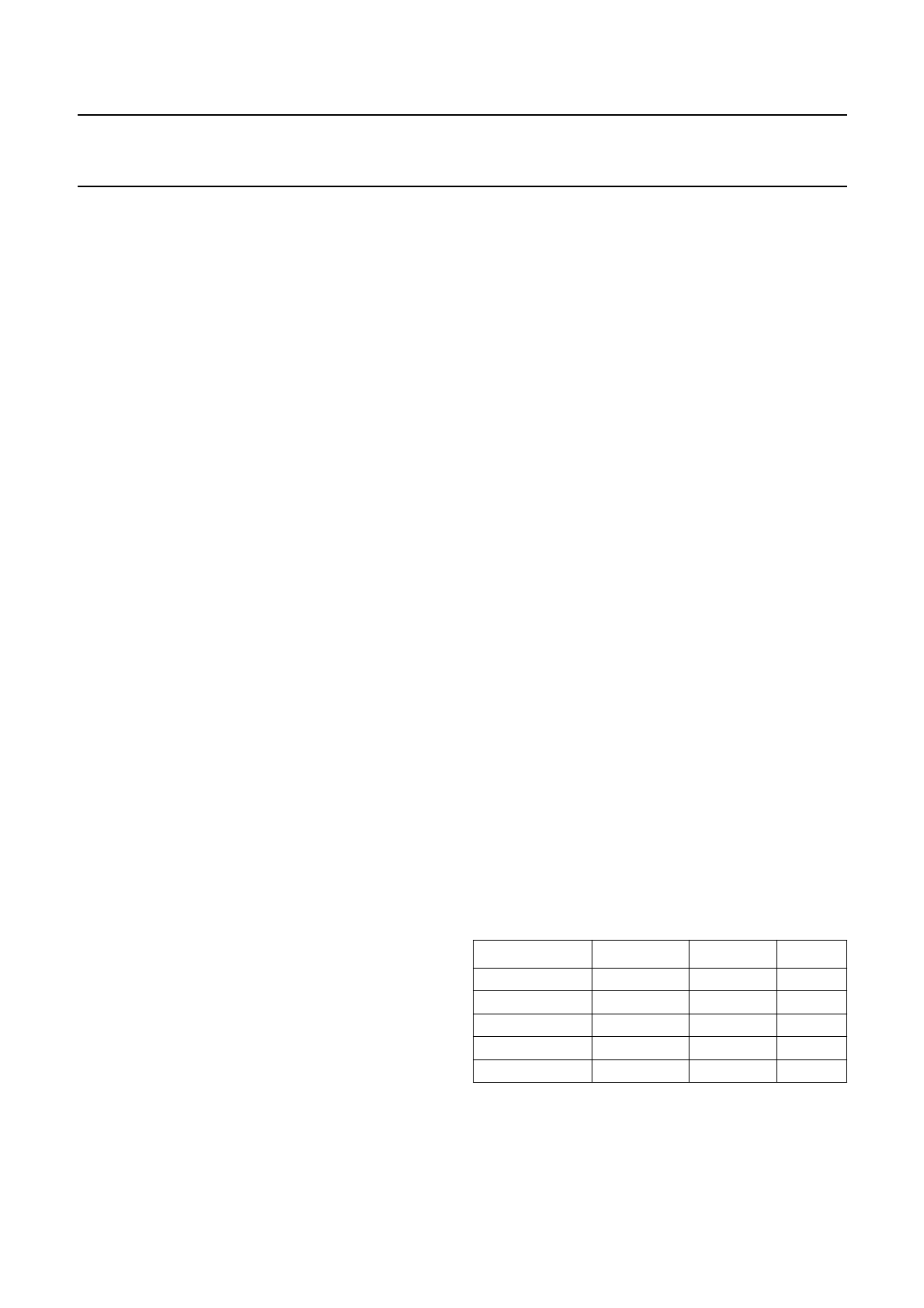
Table 1 gives a comparison between some of the more
common materials, although the majority of the figures are
only approximations as the exact values depend on a
number of variables such as thickness, deposition and
post-processing.
Table 3 Comparison of magnetoresistive sensor
materials
∆ρ is nearly independent of these factors, but r itself
increases with thickness (t ≤ 40 nm) and will decrease
during annealing. Permalloys have a low H
k
and zero
magnetostriction; the addition of C
o
will increase ∆ρ/ρ,but
H
G
0.5 H
0
H
x
+()≈
H
G
S
0
0.5
∆ρ
ρ
-------
≈
S
0
(max) 10
4–
A
m
-----
1
100
m
V
V
---------
kA
m
-------
--------------
==
Materials ρ (10
−8
Ωm) ∆ρ/ρ(%) ΙΙ
k
(∆/m)
NiFe 81:19 22 2.2 250
NiFe 86:14 15 3 200
NiCo 50:50 24 2.2 2500
NiCo 70:30 26 3.7 2500
CoFeB 72:8:20 86 0.07 2000