


2000 Sep 06 3
Philips Semiconductors
Magnetoresistive sensors for
magnetic field measurement
General
The KMZ range of magnetoresistive sensors is
characterized by high sensitivity in the detection of
magnetic fields, a wide operating temperature range, a low
and stable offset and low sensitivity to mechanical stress.
They therefore provide an excellent means of measuring
both linear and angular displacement under extreme
environmental conditions, because their very high
sensitivity means that a fairly small movement of actuating
components in, for example, cars or machinery (gear
wheels, metal rods, cogs, cams, etc.) can create
measurable changes in magnetic field. Other applications
for magnetoresistive sensors include rotational speed
measurement and current measurement.
Examples where their properties can be put to good effect
can be found in automotive applications, such as wheel
speed sensors for ABS and motor management systems
and position sensors for chassis position, throttle and
pedal position measurement. Other examples include
instrumentation and control equipment, which often
require position sensors capable of detecting
displacements in the region of tenths of a millimetre (or
even less), and in electronic ignition systems, which must
be able to determine the angular position of an internal
combustion engine with great accuracy.
Finally, because of their high sensitivity, magnetoresistive
sensors can measure very weak magnetic fields and are
thus ideal for application in electronic compasses, earth
field correction and traffic detection.
If the KMZ sensors are to be used to maximum advantage,
however, it is important to have a clear understanding of
their operating principles and characteristics, and how
their behaviour may be affected by external influences and
by their magnetic history.
Operating principles
Magnetoresistive (MR) sensors make use of the
magnetoresistive effect, the property of a current-carrying
magnetic material to change its resistivity in the presence
of an external magnetic field (the common units used for
magnetic fields are given in Table 1).
Table 1 Common magnetic units
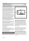
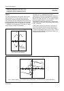
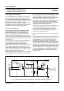
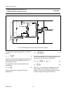
The basic operating principle of an MR sensor is shown in
Fig.2.
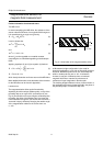
Figure 2 shows a strip of ferromagnetic material, called
permalloy (19%Fe, 81%Ni). Assume that, when no
external magnetic field is present, the permalloy has an
internal magnetization vector parallel to the current flow
(shown to flow through the permalloy from left to right).
If an external magnetic field H is applied, parallel to the
plane of the permalloy but perpendicular to the current
flow, the internal magnetization vector of the permalloy will
rotate around an angle α. As a result, the resistance of R
of the permalloy will change as a function of the rotation
angle α, as given by:
(1)
R
o
and ∆R
o
are material parameters and to achieve
optimum sensor characteristics Philips use Fe19Ni81,
which has a high R
o
value and low magnetostriction. With
this material, ∆R
o
is of the order of 3%. For more
information on materials, see Appendix 1.
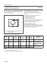
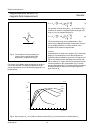
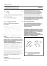
It is obvious from this quadratic equation, that the
resistance/magnetic field characteristic isnon-linear and in
addition, each value of R is not necessarily associated
with a unique value of H (see Fig.3). For more details on
the essentials of the magnetoresistive effect, please refer
to the Section “Further information for advanced users”
later in this chapter or Appendix 1, which examines the MR
effect in detail.
1 kA/m = 1.25 mTesla (in air)
1 mT = 10 Gauss
Fig.2 The magnetoresistive effect in permalloy.
handbook, halfpage
MLC127
I
Magnetization
Permalloy
H
Current
α
R = R ∆ R cos α
2
00
RR
O
∆R
O
cos
2
α+=