


2000 Sep 06 14
Philips Semiconductors
Magnetoresistive sensors for
magnetic field measurement
General
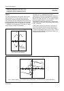
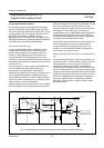
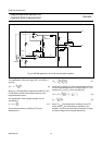
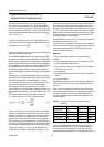
Fig.16 KMZ10B application circuit with instrumentation amplifier.
handbook, full pagewidth
MLC145
KMZ10B
offset
R2
V
O
V
S
R1
R3
OP2
R7
R4
R6
R
KTY82-110
R5
R9
R10
R12
R11
R13
R14
OP1
OP3
T
R
A
R
B
The amplification of the input stage (‘OP1’ and ‘OP2’) is
given by:
(9)
where R
T
is the temperature dependent resistance of the
KTY82 sensor and R
B
is the bridge resistance of the
magnetoresistive sensor.
The amplification of the complete amplifier can be
calculated by:
(10)
The positive temperature coefficient (TC) of the
amplification is:
(11)
For the given negative ‘TC’ of the magnetoresistive sensor
and the required amplification of the input stage ‘A1’, the
resistance ‘R
A
’ and ‘R
B
’ can be calculated by:
(12)
(13)
where TC
KTY
is the temperature coefficient of the KTY
sensor and TC
A
is the temperature coefficient of the
amplifier. This circuit also provides for adjustment of gain
and offset voltage of the magnetic-field sensor.
A1 1
R
T
R
B
+
R
A
---------------------
+=
AA1
R
14
R
10
---------
×=
TC
A
R
T
TC
KTY
×
R
A
R
B
R
T
++
-----------------------------------
=
R
B
R
T
TC
KTY
TC
A
------------------
1
1
A1
-------
–
1–×
×=
R
A
R
T
R
B
+
A1 1–
---------------------
=