


2000 Sep 06 23
Philips Semiconductors
Magnetoresistive sensors for
magnetic field measurement
General
WEAK FIELD MEASUREMENT
Contents
• Fundamental measurement techniques
• Application note AN00022: Electronic compass design
using KMZ51 and KMZ52
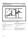
• Application circuit: signal conditioning unit for compass
• Example 1: Earth geomagnetic field compensation in
CRT’s
• Example 2: Traffic detection
• Example 3: Measurement of current.
Fundamental measurement techniques
Measurement of weak magnetic fields such as the earth’s
geomagnetic field (which has a typical strength of between
approximately 30 A/m and 50 A/m), or fields resulting from
very small currents, requires a sensor with very high
sensitivity. With their inherent high sensitivity,
magnetoresistive sensors are extremely well suited to
sensing very small fields.
Philips’ magnetoresistive sensors are by nature bi-stable
(refer to Appendix 2). ‘Standard’ techniques used to
stabilize such sensors, including the applicationof a strong
field in the x-direction (H
x
) from a permanent stabilization
magnet, are unsuitable as they reduce the sensor’s
sensitivity to fields in the measurement, or y-direction (H
y
).
(Refer to Appendix 2, Fig. A2.2).
To avoid this loss in sensitivity, magnetoresistive sensors
can instead be stabilized by applying brief, strong
non-permanent field pulses of very short duration (a few
µs). This magnetic field, which can be easily generated by
simply winding a coil around the sensor, has the same
stabilizing effect as a permanent magnet, but as it is only
present for a very short duration, after the pulse there is no
loss of sensitivity. Modern magnetoresistive sensors
specifically designed for weak field applications
incorporate this coil on the silicon.
However, when measuring weak fields, second order
effects such as sensor offset and temperature effects can
greatly reduce both the sensitivity and accuracy of MR
sensors. Compensation techniques are required to
suppress these effects.
O
FFSET COMPENSATION BY ‘FLIPPING’
Despite electrical trimming, MR sensors may have a
maximum offset voltage of ±1.5 mV/V. In addition to this
static offset, an offset drift due to temperature variations of
about 6 (µV/V)K
−1
can be expected and assuming an
ambient temperature up to 100 °C, the resulting offset can
be of the order of 2 mV/V.
Taking these factors into account, with no external field a
sensor with a typical sensitivity of 15 mV/V (kA/m)
−1
can
have an offset equivalent to a field of 130 A/m, which is
itself about four times the strength of a typical weak field
such as the earth’s geomagnetic field. Clearly, measures
to compensate for the sensor offset value have to be
implemented in weak field applications.
A technique called ‘flipping’ (patented by Philips) can be
used to control the sensor. Comparable to the ‘chopping’
technique used in the amplification of small electrical
signals, it not only stabilizes the sensor but also eliminates
the described offset effects.
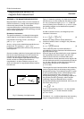
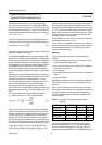
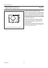
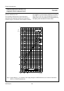
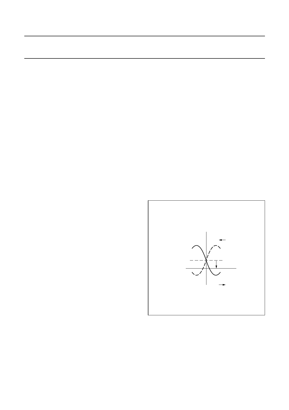
When the bi-stable sensor is placed in a controlled,
reversible external magnetic field, the polarity of the
premagnetization (M
x
) of the sensor strips can be switched
or flipped between the two output characteristics (see
Fig.27).
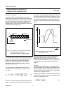
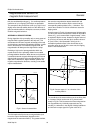
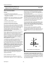
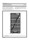
This reversible external magnetic field can be easily
achieved with a coil wound around the sensor, consisting
of current carrying wires, as described above. Depending
on the direction of current pulses through this coil, positive
and negative flipping fields in the x-direction (+H
x
and −H
x
)
are generated (see Fig.28).
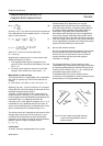
Fig.27 Butterfly curve including offset.
MLC764
V
O
M
x
offset
H
y
M
x