


2000 Sep 06 17
Philips Semiconductors
Magnetoresistive sensors for
magnetic field measurement
General
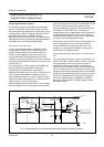
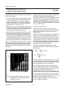
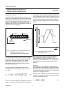
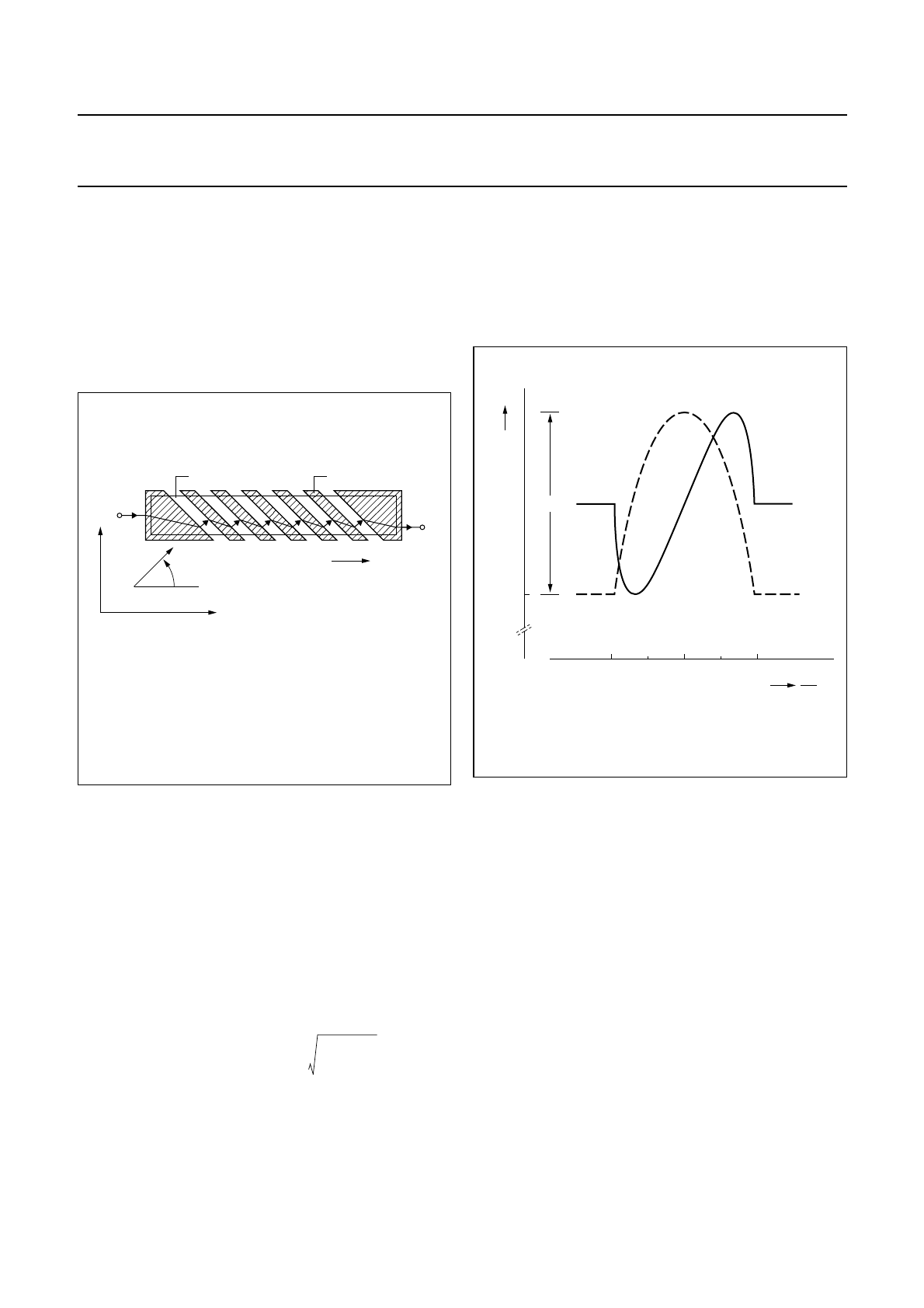
BARBER-POLE SENSORS
A number of Philips’ magnetoresistive sensors use a
‘barber-pole’ construction to linearize the R-H relationship,
incorporating slanted strips of a good conductor to rotate
the current. This type of sensor has the widest range of
linearity, smaller resistance and the least associated
distortion than any other form of linearization, and is well
suited to medium and high fields.
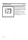
The current takes the shortest route in the high-resistivity
gaps which, as shown in Fig 19, is perpendicular to the
barber-poles. Barber-poles inclined in the opposite
direction will result in the opposite sign for the R-H
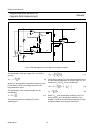
characteristic, making it extremely simple to realize a
Wheatstone bridge set-up.
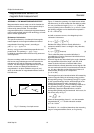
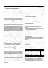
The signal voltage of a Barber-pole sensor may be
calculated from the basic equation (1) with Θ = φ + 45˚
(θ = + 45˚):
U
BP
=ρ
⊥
l (9)
where a is a constant arising from the partial shorting of the
resistor, amounting to 0.25 if barber-poles and gaps have
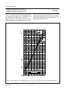
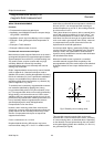
equal widths. The characteristic is plotted in Fig 20 and it
can be seen that for small values of H
y
relative to H
0
, the
R-H dependence is linear. In fact this equation gives the
same linear R-H dependence as the planar Hall-effect
sensor, but it has the magnitude of the magnetoresistive
sensor.
Barber-pole sensors require a certain magnetization
state. A bias field of several hundred A/m can be
generated by the sensing current alone, but this is not
sufficient for sensor stabilization, so can be neglected. In
most applications, an external field is applied for this
purpose.
Sensitivity
Due to the high demagnetization, in most applications
field components in the z-direction (perpendicular to the
layer plane) can be ignored. Nearly all sensors are most
sensitive to fields in the y-direction, with H
x
only having a
limited or even negligible influence.
Definition of the sensitivity S contains the signal and field
variations (DU and DH), as well as the operating voltage
U
0
(as D
U
is proportional to U
0
):
S
o
= (10)
Fig.19 Linearization of the magnetoresistive effect
with barber-poles (current and
magnetization shown in quiescent state).
handbook, halfpage
Magnetization
Barber pole
Permalloy
Ι
Ι
y
+
Ι
−
x
ϑ
MBH614
L
wt
------
α1
1
2
---
∆ρ
ρ
-------
∆ρ
ρ
-------
±
H
y
H
0
-------
1
H
y
H
0
-------
2
–+
Fig.20 Calculated R-H characteristic of a
barber-pole sensor.
handbook, halfpage
MBH615
−0.5 0
0
R
0
R
∆R
0.5 1
H
Y
H
0
−1
∆U
∆H
--------
1
U
0
-------
∆U
U
0
∆H
----------------
=