


2000 Sep 06 22
Philips Semiconductors
Magnetoresistive sensors for
magnetic field measurement
General
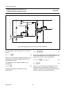
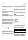
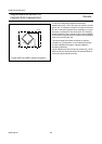
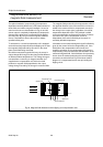
In one pair of diagonally opposed elements the
barber-poles are at +45˚ to the strip axis, with the second
pair at −45˚. A resistance increase in one pair of elements
due to an external magnetic field is matched by an equal
decrease in resistance of the second pair. The resulting
bridge imbalance is then a linear function of the amplitude
of the external magnetic field in the plane of the permalloy
strips normal to the strip axis.
This layout largely eliminates the effects of ambient
variations (e.g. temperature) on the individual elements
and also magnifies the degree of bridge imbalance,
increasing sensitivity.
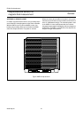
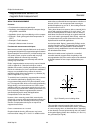
Fig 26 indicates two further trimming resistors (R
T
) which
allow the sensors electrical offset to be trimmed down to
zero during the production process.
Fig.26 KMZ10 and KMZ11 bridge configuration.
handbook, halfpage
MLC129
2 1
GND
V
O
V
CC
V
O
R
T
R
T
34