


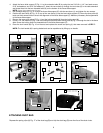
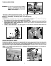
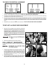
1. This miter saw will cut any angle from 0° to 47° right and left. Turn the locking knob (A) Fig. 21 counter-clockwise, depress
the lock lever (B), and rotate the table.
2. The compound miter saw is equipped with positive stops at 0°, 15°, 22.5°, 31.62°, and 45° left and right.
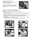
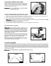
3. The center line (C) Fig. 22 on the cursor indicates the actual angle of cut. Each scale line (B) represents 1°. When the center
line (C) is moved from one line to the next on the scale, the angle of the cut is changed by 1°.
4. The pointer is provided with two additional lines (D) and (E) Fig. 22. This allows movement of 1/2°. For example, assume
the center line (C) is pointing to the 10° mark on the scale, and the angle of cut is 1/2° to the right. Move the control arm
until the right line (E) lines up with the next line on the scale. If you change the angle of cut 1/2° to the left, use the left line
(D).
ROTATING TABLE FOR MITER CUTTING
10
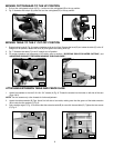
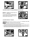
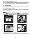
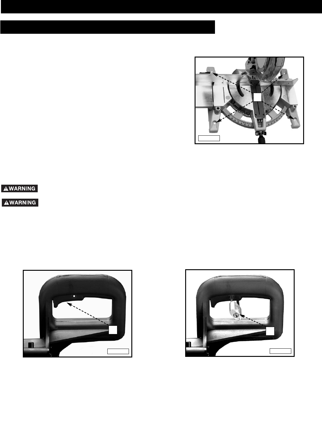
To start the machine, depress the switch trigger (A) Fig. 19. To stop the machine, release the switch trigger.
This saw is equipped with an automatic electric blade brake. As soon as the switch trigger (A) Fig. 19 is released, the electric
brake is activated and stops the blade in seconds.
A rotating saw blade can be dangerous. After completing the cut, release the switch trigger (A) Fig. 19
to activate the blade brake. Keep the cuttinghead down until the blade has come to a complete stop.
The torque developed during braking may loosen the arbor screw. The arbor screw should be checked
periodically and tightened if necessary
.
LOCKING SWITCH IN THE “OFF” POSITION
IMPORTANT: When the miter saw is not in use, the switch should be locked in the "OFF" position, using a padlock (B) Fig.
20 with a 3/16" diameter shackle to prevent unauthorized use of the saw.
STARTING AND STOPPING MACHINE
A
B
Fig. 19
Fig. 20
OPERATION
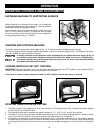
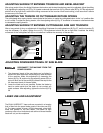
Before operating your miter saw, firmly mount it to a workbench
or other supporting surface. Four holes (A) Fig. 18 are provided for
fastening the saw to a supporting surface.
When frequently moving the saw from place to place, mount the
saw on a 3/4” piece of plywood. The saw can then be easily
moved from place to place and the plywood can be clamped to
the supporting surface using “C” clamps.
FASTENING MACHINE TO SUPPORTING SURFACE
A
Fig. 18
In the event of a power outage, always lock switch in “OFF” position until the main power is restored.
OPERATING CONTROLS AND ADJUSTMENTS