


14
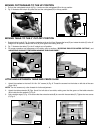
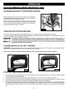
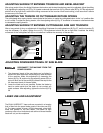
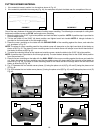
ADJUSTING SLIDING FIT BETWEEN TRUNNION AND BEVEL BRACKET
After a long period of time, the sliding fit between the trunnion and the bevel bracket may need to be adjusted. Adjust the sliding
fit by tightening the adjusting nut (C) Fig. 36, located underneath the bevel lock (A) Fig. 36 and collar (B) Fig. 36.
This adjustment
should not be so tight that it restricts the tilting movement of the trunnion when bevel cutting, or so loose that it affects
the accuracy of the saw cut.
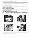
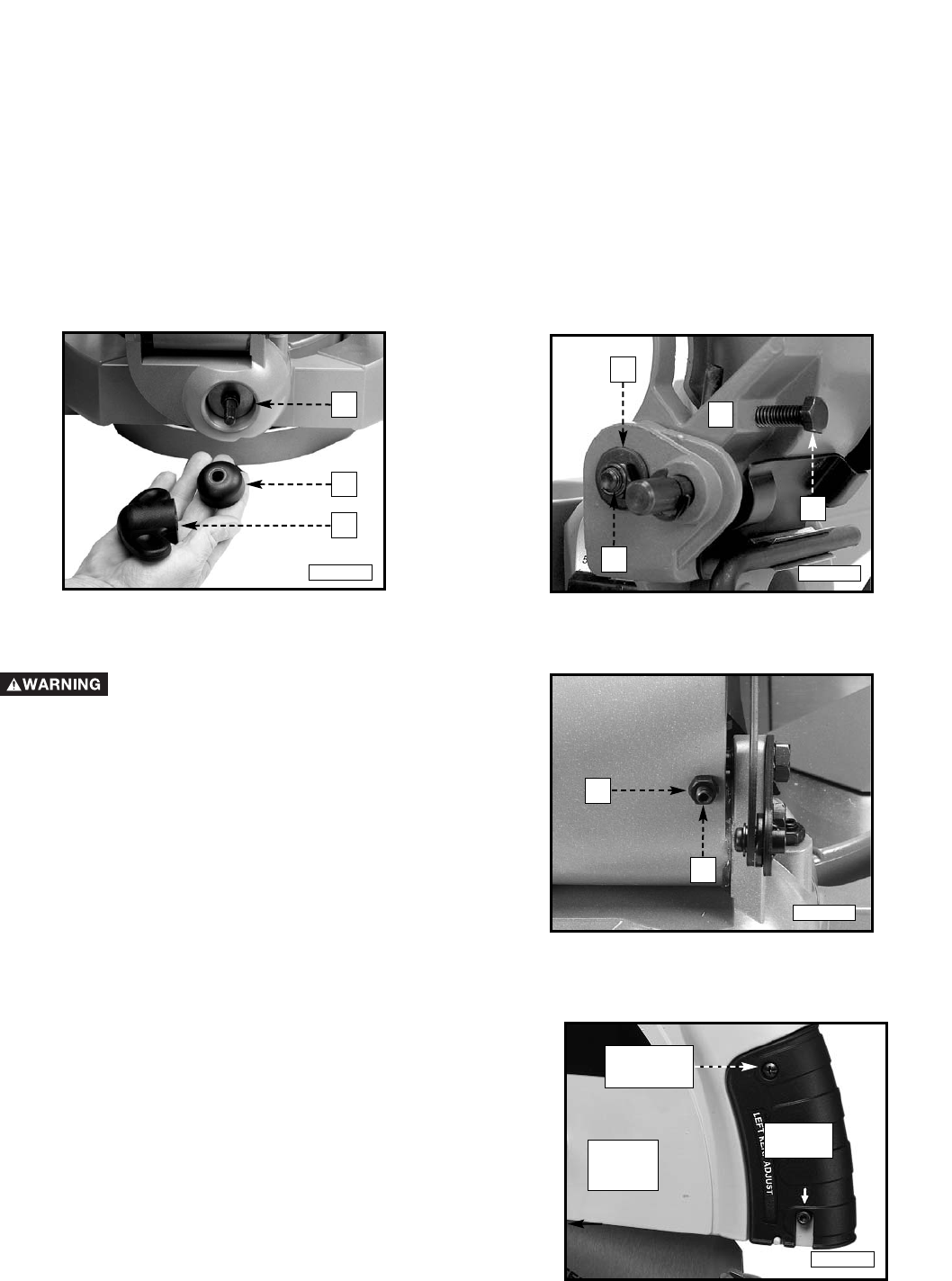
ADJUSTING THE TENSION OF CUTTINGHEAD RETURN SPRING
The cuttinghead return spring tension was adjusted at the factory to make the cuttinghead return to the "up" position after
a cut is made. To adjust the spring tension, turn the adjusting screw (A) Fig. 37 clockwise to increase or counterclockwise
to decrease the spring tension.
ADJUSTING SLIDING FIT BETWEEN CUTTINGHEAD ARM AND TRUNNION
After a long period of time, an adjustment of the sliding fit between the cuttinghead arm (B) Fig. 37, and the trunnion (C)
may be necessary. To adjust, tighten the nut (D). This adjustment should not be so tight that it restricts the sliding
movement of the cuttinghead arm (B) or so loose that it affects the accuracy of the saw cut.
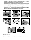
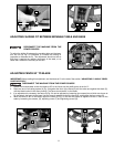
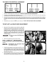
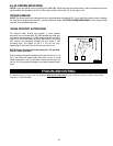
1. The downward travel of the saw blade can be limited to
prevent the saw blade from contacting any metal surfaces
of the machine. Make this adjustment by loosening the
locknut (A) Fig. 38, and turning the adjusting screw (B) in or
out until other end of the screw (B) contacts the stop at the
full downward travel of the saw blade.
2. Lower the blade as far as possible. Rotate the blade by
hand to make certain that the teeth do not contact any
metal surfaces. After adjusting, tighten the locknut (A) Fig.
38.
A
B
C
A
B
C
D
Fig. 36
Fig. 37
ADJUSTING DOWNWARD TRAVEL OF SAW BLADE
DISCONNECT THE MACHINE FROM THE
POWER SOURCE.
Fig. 38
B
A
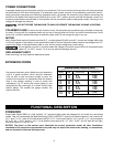
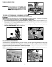
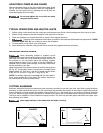
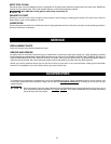
LASER USE AND ADJUSTMENT
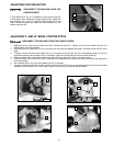
LASER
UNIT
UPPER
BLADE
GUARD
PHILLIPS
SCREW
The DUAL LASERLOC
™
laser units are mounted in a housing
that is fitted into the upper blade guard of the miter saw (Fig.
A). The lasers project a beam of light downward, along both
sides and parallel to the saw blade. This beam of light
produces a line-of-cut indicator (a red outline of where the saw
blade will cut) on the workpiece.
Fig. A