


13
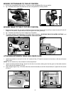
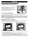
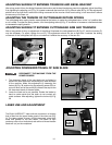
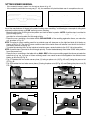
1. Adjust the saw so that both the bevel and miter pointers are set at 0°. Tighten the bevel lock handle and lock the
cuttinghead in the down position.
2. Place one end of a square (A) Fig. 32 on the table and the other end against the blade. The blade should be 90° to the
table.
3. To adjust, loosen the bevel lock handle (H) Fig. 33. Loosen the locknut (B) and turn the adjusting screw (C) with the
provided wrenches until the blade is 90° to the table. Tighten the locknut (B) and the bevel lock handle (H).
4. When the blade is 90° to the table, adjust the pointer to line up with the 0° mark on the bevel scale.
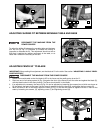
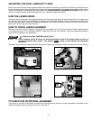
5. Loosen the bevel lock handle (H) Fig. 33, and move the cuttinghead all the way to the left bevel position and tighten the
bevel lock handle.
6. Use a square (A) Fig. 34 to see if the blade is at 45° to the table.
7. To adjust, loosen the bevel lock handle. Loosen the locknut (E) Fig. 35 and turn the adjusting screw (F) with the provided
wrenches, until the blade is 45° to the table. Tighten the locknut (E) and the bevel lock handle.
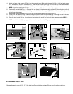
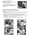
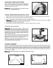
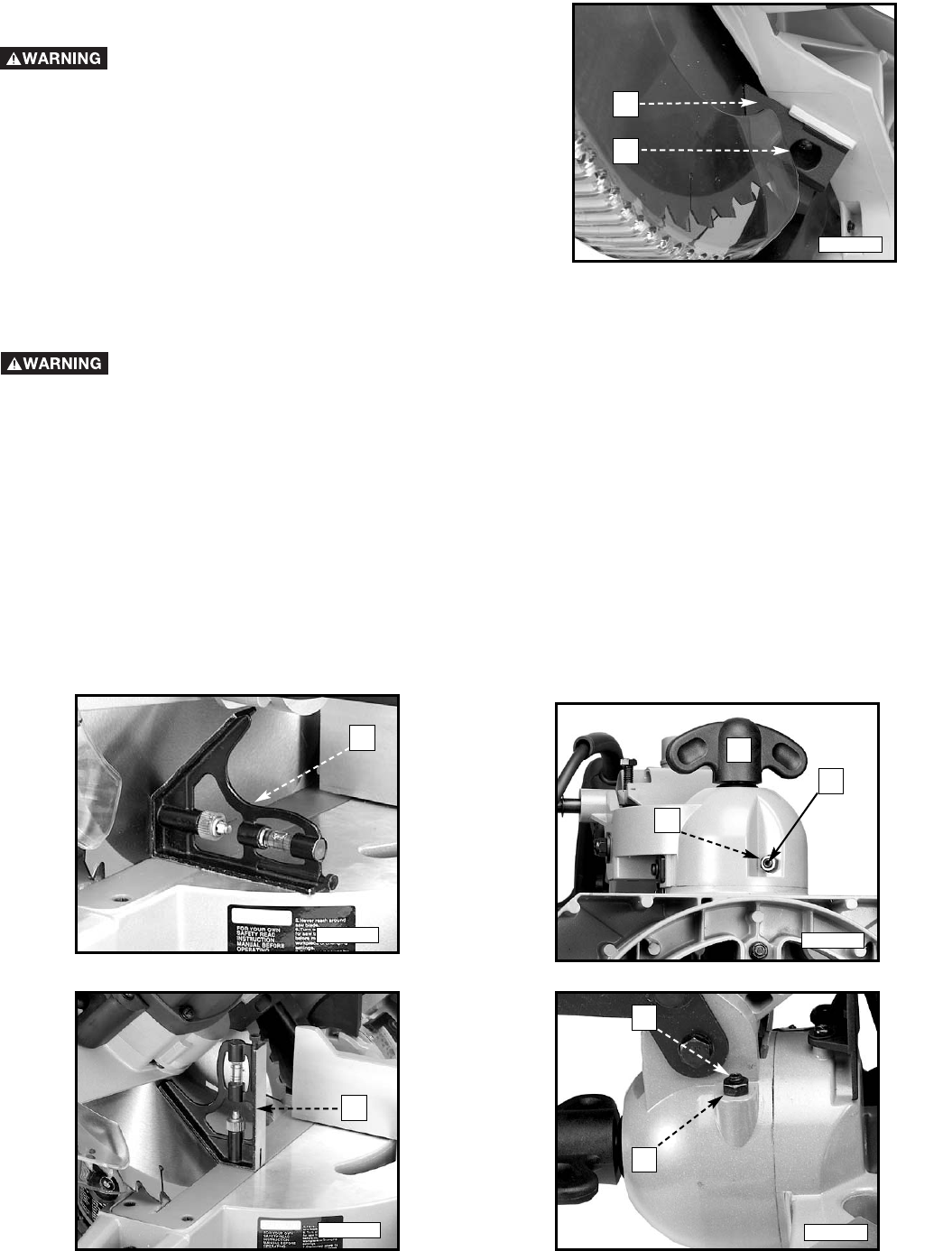
ADJUSTING CHIP DEFLECTOR
DISCONNECT THE MACHINE FROM THE
POWER SOURCE.
A chip deflector (A) Fig. 31 is supplied to help prevent scrap or
cut-off pieces from entering the upper blade guard. Adjust the
chip deflector (A) so that it is almost touching the side of the
blade. Loosen the screw (B), adjust the chip deflector (A), and
tighten the screw (B).
A
B
ADJUSTING 0° AND 45° BEVEL POSITIVE STOPS
Fig. 31
Fig. 32
Fig. 33
Fig. 35
DISCONNECT THE MACHINE FROM THE POWER SOURCE.
A
H
B
C
A
Fig. 34
E
F