


19
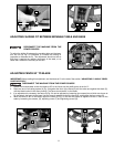
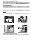
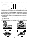
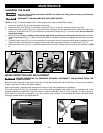
For support when cutting long pieces, a work support
extension can be constructed. Fig. 49 illustrates the miter saw
mounted to two standard 2 x 4’s (A). Fasten the four mounting
legs (two of which are shown at (B) Fig. 49) to the 2 x 4’s, using
four screws (not supplied) through the four holes in the
mounting legs. The length of the 2 x 4’s (A) can vary,
depending on the kind of work that will need to be cut.
NOTE: Ensure that the top of the support 2 x 4’s are level
with the miter saw table.
This is critical because the distance from the top of the 2 x 4’s
(A) to the miter saw table varies from saw to saw. In most
cases, standard 2 x 4’s (C) can used. If these are too high, cut
the 2 x 4s (C) to provide this height or use other properly-sized
wood
A
C
B
WORK SUPPORT EXTENSIONS
Fig. 49
TROUBLESHOOTING
For assistance with your tool, visit our website at www.porter-cable.com for a list of service centers or call the Porter-Cable
help line at 1-800-487-8665.
45-45 CROWN MOULDING
NOTE: If you are cutting crown moulding that is 45°-45°, follow the same procedure above, with the exception that the
bevel position will always be at 30° and the miter position will be 35-1/4° to the right or left.
OTHER ANGLES
NOTE: The above instructions are assuming the angle between the walls is 90°. If you need help cutting crown moulding
for walls set at angles other than 90°, see the instruction sheet “CUTTING CROWN MOULDING” on the Porter-Cable
web site at www.portercable.com.