


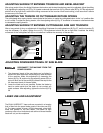
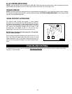
VERTICAL
ALIGNMENT
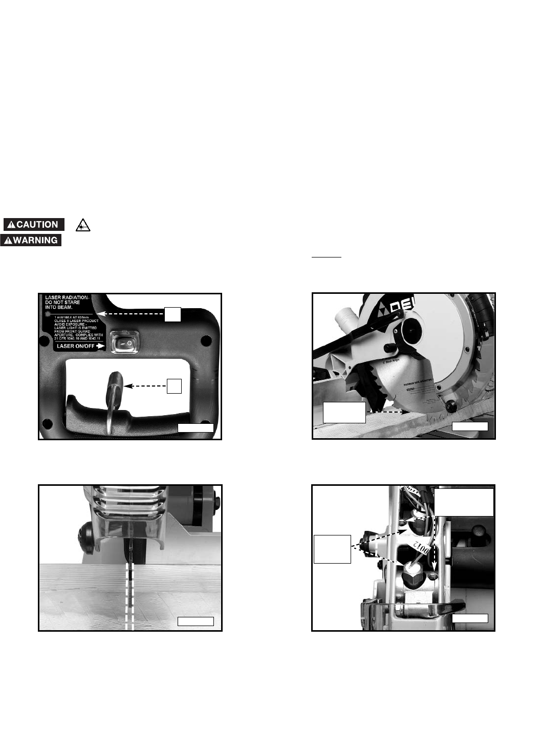
SET SCREWS
15
PARTIAL
CUT
BRASS
HEX
NUT
ADJUSTING THE DUAL LASERLOC
™
LINES
Each of the laser lines have been aligned parallel to the blade at the factory and should not need any adjustment prior
to use. However, left-to-right adjustment to the laser lines may be necessary if you change to a thicker or thinner kerf
blade. For information on changing your blade, refer to the "MAINTENANCE: CHANGING THE BLADE" section of this
manual. To adjust the laser lines to the edge of the cut, follow the instructions below.
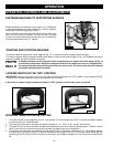
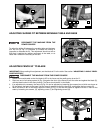
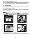
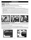
HOW THE LASERS WORK
The laser units are mounted in a housing that is fitted into the upper blade guard of the miter saw (Fig. A). The laser units
are aligned to the original equipment blade at the factory and are secured in place. A test cut has been made with each
saw to verify laser setup. If your saw becomes misaligned or you desire additional precision, this guide is intended to
assist you in fine tuning your laser miter saw.
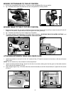
HOW TO CHECK LASER ALIGNMENT
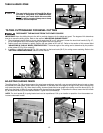
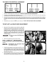
Make sure the saw is set to 0 degrees, miter and bevel, and clamp a 2"x 6" board on the saw. Create a partial test cut
in the workpiece (Fig. C). Turn the laser “ON/OFF” switch (Fig. B) to the “ON” position. Leave the workpiece clamped in
place for the remainder of the adjustment.
Observe the laser CAUTION label (L) Fig. B.
Place a padlock (A) Fig. B (with 3/16" shackle) through the hole in the trigger switch and lock to
prevent accidental motor startup. This padlock MUST
remain in place during the adjustment
procedure.
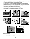
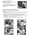
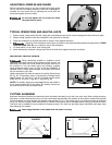
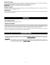
The laser lines are properly positioned when the beams of light fall on the edge of the cut created by the blade (Fig. D).
L
A
Fig. B
Fig. C
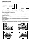
The rotation of the lines is set parallel at the factory and permanently secured. No user adjustment is available for the
rotational alignment. Never twist the brass hex nuts in Fig. E.
TO CHECK FOR ROTATIONAL ALIGNMENT
Fig. D
Fig. E