


9
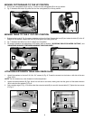
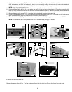
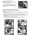
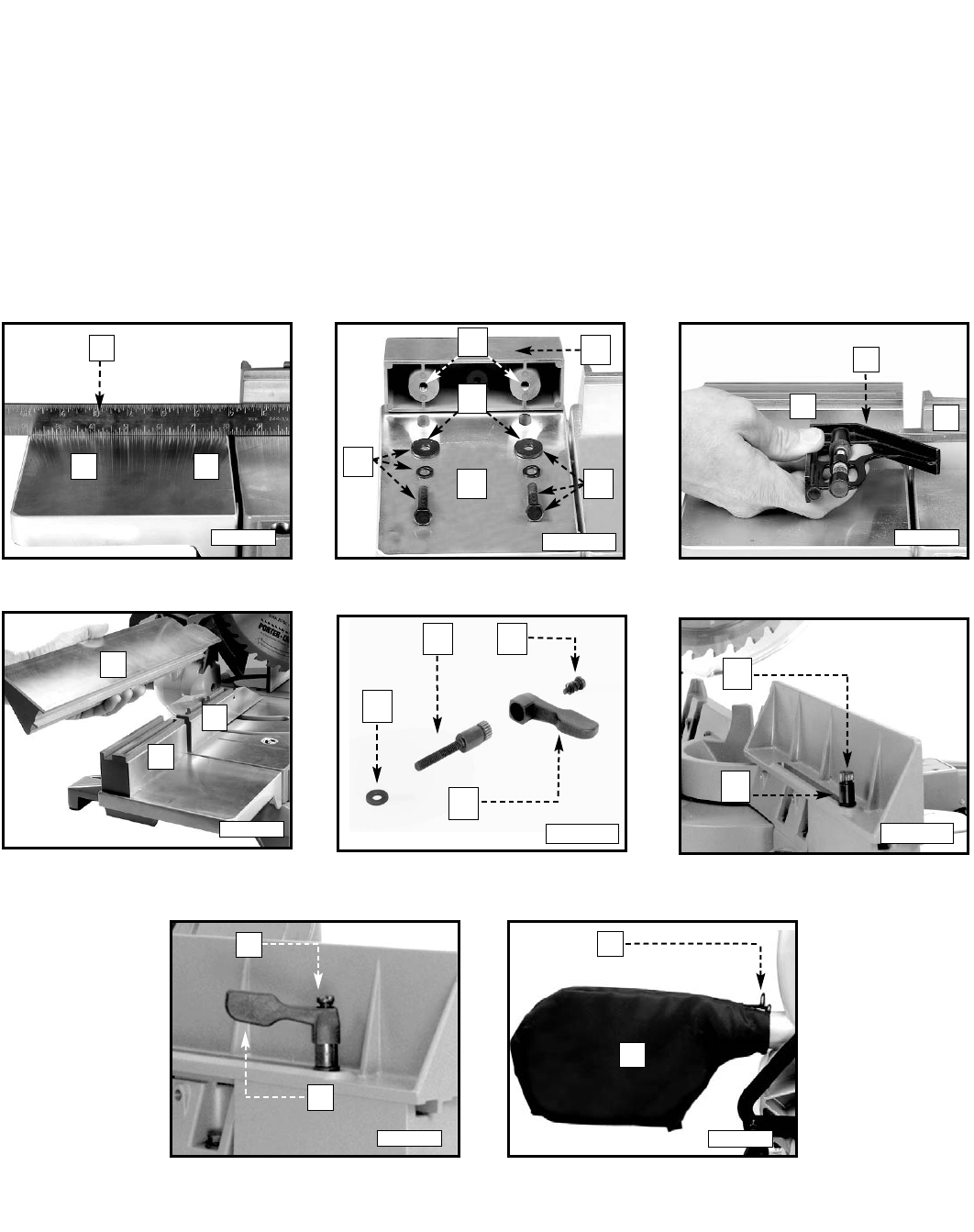
4. Attach the fence slide support (E) Fig. 11 to the extension table (B) by using the two 5/16-18 x1-1/4” hex head screws,
5/16” lockwashers, and 5/16” flat washers (F). Insert the two screws up through the two holes (G) in the table extension
and thread them into the two threaded holes (H) on the bottom of the fence slide support.
NOTE: Leave the screws loose for now.
5. Use a straight edge (C) Fig. 12 to align the fence slide support (E) with the saw fence (J), and tighten the two screws.
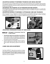
6. Position the fence slide (K) Fig. 13 on top of the saw fence (J) and the fence slide support (E). Move the fence slide (K)
back and forth several times to check the alignment of the fence slide support (E). Make any necessary final adjustments
to the fence slide support.
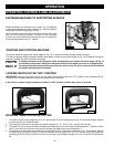
7. Remove the screw and spring (E) Fig. 14 and the locking handle (M) from the locking stud (N).
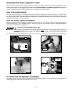
8. PLace a 1/4" flat washer (O) Fig. 14 on the locking stud (N) and insert locking stud (N) Fig. 15 through the slot in the fence
slide. Screw the locking stud into threaded hole in the fence slide support (E).
9. Place the lock handle (M) Fig. 16 on the stud and replace the screw and spring (L) that were removed in STEP 7.
NOTE: The lock handle (M) is spring-loaded and can be repositioned by lifting up on handle.
B
E
H
G
F
F
Fig. 11
E
J
C
Fig. 12
J
E
K
Fig. 13
O
N
M
E
Fig. 14
E
N
M
L
Fig. 15
Fig. 16
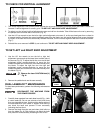
Depress the spring clips (A) Fig. 17 of the dust bag (B) and clip the dust bag (B) over the ribs of the dust chute.
ATTACHING DUST BAG
B
A
Fig. 17
Fig. 10
C
B
D