


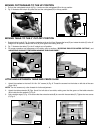
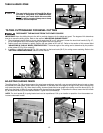
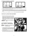

To adjust the sliding fit between the movable table and the base,
turn the nut (A) Fig. 23 clockwise to increase the sliding fit
(opposite to decrease the fit). This adjustment should not be so
tight that it restricts the rotating movement of the table, or so
loose that it affects the accuracy of the saw.
11
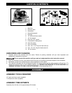
A
B
C
E
D
B
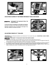
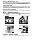
DISCONNECT THE MACHINE FROM THE
POWER SOURCE.
ADJUSTING SLIDING FIT BETWEEN MOVABLE TABLE AND BASE
A
Fig. 21 Fig. 22
Fig. 23
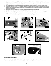
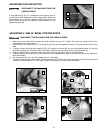
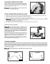
IMPORTANT: Before making this adjustment, set the blade at 0° to the table. See section “ADJUSTING 0° AND 45° BEVEL
POSITIVE STOPS.”
1. Rotate the movable table so that the blade is 90° to the fence and the positive stop is set for 0°.
2. Place one end of a framing square (A) Fig. 24 against the front of the fence (B) and the other end against the blade (C),
with the blade locked in the down position. The fence should be 90° to the blade.
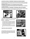
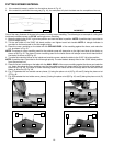
3. If an adjustment is necessary, the fence (B) Fig. 24 can be adjusted by loosening four screws (two of which are shown at
D), that attach the fence to the base. Use the wrench supplied. Adjust the fence (B), and tighten the four screws (D).
4. When the fence is 90° to the blade, adjust the cursor (F) Fig. 25, so that the pointer is aligned with the 0° mark on the
scale by loosening two screws, (G), adjusting cursor (F) and tightening screws (G).
ADJUSTING FENCE 90° TO BLADE
DISCONNECT THE MACHINE FROM THE POWER SOURCE.
A
C
B
D
G
F
Fig. 24
Fig. 25