


20
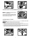
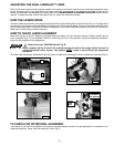
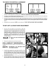
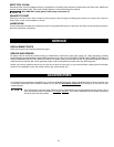
BRUSH INSPECTION AND REPLACEMENT
BEFORE INSPECTING OR REMOVING BRUSHES, DISCONNECT THE MACHINE FROM THE
POWER SOURCE.
Brush life varies, depends on the load on the motor. Check the brushes after the first 50 hours of use of a new machine,
or after a new set of brushes has been installed.
After the first check, examine them after about 10 hours of use, until replacement is necessary.
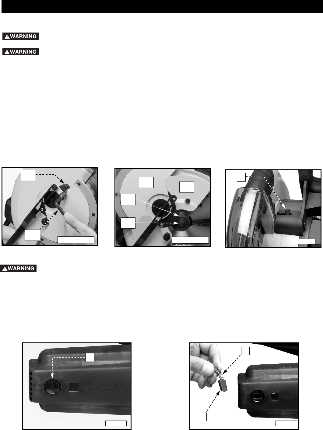
The brush holders (A) Fig. 53, are located on the motor housing opposite each other. Fig. 54, illustrates one of the
brushes removed for inspection. When the carbon on either brush (B) is worn to 3/16" in length, or if either spring or
shunt wire (C) is burned or damaged in any way, replace both brushes. If the brushes are found serviceable after
removing, reinstall them in the same position.
A
B
C
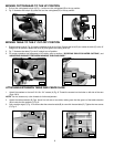
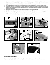
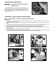
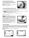
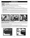
CHANGING THE BLADE
Use only cross-cutting saw blades. DO NOT use blades with deep gullets as they can deflect and
contact the guard
NOTE: Use only 12" diameter blades with 1" arbor holes that are rated for 4000 RPM or higher.
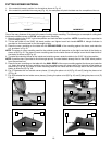
1. Loosen the screw (A) Fig. 50 with the supplied wrench (B).
2. Rotate the arbor cover (C) Fig. 51, and lower the guard (D) Fig. 51 to the rear, exposing the arbor screw (E).
3. Remove the arbor screw (E) Fig. 51 by turning the screw clockwise with the supplied wrench, while at the same time,
pressing in on the arbor lock (F) Fig. 52. Remove the outside blade flange (G) Fig. 51, and saw blade. Do not remove the
inside blade flange.
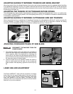
4. Attach the new saw blade, making certain that the teeth of the saw blade are pointing down at the front, and attach
outside blade flange (G) Fig. 51. Check to see that the flats on outside blade flange are engaged with the flats on the arbor
shaft.
5. Thread the arbor screw (E) Fig. 51 into the saw arbor by turning the screw (E) counterclockwise as far as possible by hand.
Tighten the arbor screw (E) with the supplied wrench while at the same time pressing in on arbor lock (F) Fig. 52.
6. Rotate the arbor cover (C) Fig. 51, and lower the guard (D) to the front. Tighten the screw (A) that was loosened in STEP
3.
MAINTENANCE
DISCONNECT THE MACHINE FROM THE POWER SOURCE.
A
B
C
D
G
E
Fig. 50
Fig. 51
Fig. 52
F
Fig. 53 Fig. 54