


14
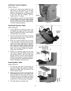
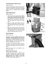
Installing Trunnion Support
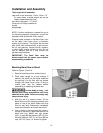
Refer to Figure 21.
1. Use the two locating pins attached to the
saw body to help position the trunnion
support. Attach trunnion support to saw
body with two M8x30 hex cap screws (HP1-
J) and two M8 lock washers (HP1-F).
Tighten with a 1/2” wrench.
2. Thread M8 hex nut (HP1-H) onto the M8x80
hex cap screw (HP1-K) and install into the
trunnion support as shown. Finger tighten
the hex nut; this will be fully tightened later
for the 90° table stop setting.
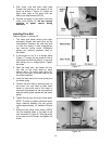
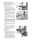
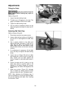
Installing Extension Table
Refer to Figure 22.
1. Install a M8 hex nut (HP2-C) on each of the
four M8x20 set screws (HP2-D), then install
these set screws into the four outer holes of
the level board (G), as shown.
2. Leave the set screws flush with the top side
of the level board for now. These will be
adjusted later during leveling.
3. Place four spacers (HP2-B) over the holes
in the saw body, and place the level board
on them, as shown. Align the four innermost
holes of the level board with the spacers,
and insert four M8x65 socket head cap
screws (HP2-H). Firmly tighten these screws
down into the base through the spacers,
using a 6mm hex wrench.
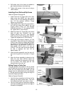
4. Position the extension table (K) over the
level board. Insert four M6x25 socket head
cap screws (HP2-E) with four M6 lock
washers (HP2-F) and four M6 flat washers
(HP2-G) up through the remaining holes of
the plate and into the underside of extension
table. Hand tighten only at this time.
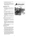
Installing Main Table
Refer to Figure 23.
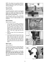
1. To mount the main table, remove table pin
by pulling it straight out, twisting it if needed.
Remove the table insert by pushing it up
from beneath the table.
2. Rotate the table so that the saw blade will
slide through the slot in the table. Then
orient the table so the screws will slide into
the holes on the trunnion support, as shown
in Figure 23. Attach the two table locking
knobs (HP1-E) to these screws and tighten.
3. Re-install table pin and table insert.
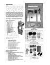
Figure 20
Figure 21
Figure 22