


17
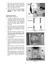
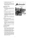
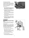
3. Tighten both screws on the front rail (HP4-L,
Figure 26) with a 10mm wrench.
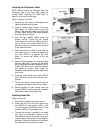
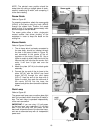
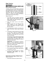
4. Adjust the height of the sliding pad at the
rear of the fence (Figure 29) if further
adjustment is needed to even the gap along
the length of the fence.
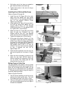
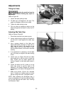
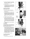
Aligning Fence to Blade
Refer to Figure 31.
1. Place the table at 90-degrees. (Make sure
the 90° Table Stop setting has been verified
– see page 20.)
2. Lock the fence to the guide rail with the
handle.
3. Place a square on the table and against the
fence, as shown in Figure 31.
4. If the fence is not square to the table,
slightly loosen the two screws in the front
rail (see Figure 26) and raise or lower one
end of the front rail assembly until fence is
square to table.
5. Re-tighten screws. The fence face is now
square to the table, and thus parallel to the
blade.
The fence must also be set so that it aligns with
the blade front-to-back, as follows:
6. Move the fence so that it just contacts the
blade without bending it, and lock the fence
to the guide rail.
7. Check that the fence is aligned with the
blade; that is, it contacts front and back of
blade evenly. If the fence does not align with
the blade, loosen the four hex cap screws
(HP4-H).
8. Align the fence with the blade, then tighten
the four hex cap screws.
Checking zero setting
Refer to Figure 31.
1. With the fence now aligned with the blade,
and still contacting the blade as shown in
Figure 31, check to see that the pointer is
aligned with zero on the guide rail scale.
2. If minor adjustment is necessary, loosen the
screw that holds the pointer in place, and
adjust the pointer. Re-tighten the screw.
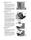
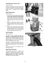
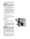
3. If major adjustment is necessary, loosen the
guide rail screws (HP4-L, Figure 27), and
slide the entire fence/guide rail together until
the fence just contacts the blade. Re-tighten
guide rail screws, and make further minor
adjustment with the pointer.
Figure 30
Figure 31