


16
4. Shift either end of the fence as needed to
gain identical distance from table top.
5. Tighten both screws in the rear rail using a
10mm wrench.
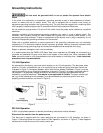
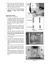
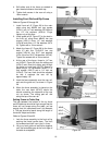
Installing Front Rail and Rip Fence
Refer to Figures 26 through 29.
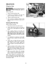
1. Install front rail (E, Figure 26) to the main
table using two M6x20 hex cap screws
(HP4-L), two 1/4" lock washers (HP4-M) and
two 1/4" flat washers (HP4-N). Finger
tighten only at this time.
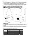
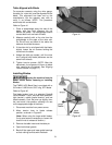
2. Install guide rail (B, Figure 27) to the slots in
the front rail using three M6x20 hex cap
screws (HP4-L), three 1/4" lock washers
(HP4-M) and three 1/4" flat washers (HP4-
N). Tighten with a 10mm wrench.
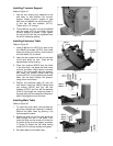
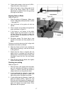
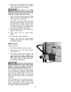
3. Attach the fence (C, Figure 28) to the fence
body (P) with four 5/16”x3/4” hex cap
screws (HP4-H), four 5/16” lock washers
(HP4-J) and four 5/16” flat washers (HP4-K).
Tighten the screws with a 12mm wrench.
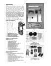
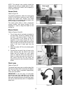
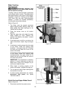
4. At the rear of the fence, thread a 1/4” hex
nut (HP4-D, Figure 29) onto the sliding pad
(HP4-G) and insert the sliding pad through
the fence and rear hook (HP4-C). Secure in
place using a 1/4” flat washer (HP4-E), 1/4”
lock washer (HP4-F) and a 1/4” hex nut
(HP4-D). The rear hook should be adjusted
so that it overlaps the rear rail by
approximately 1/8".
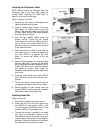
5. Hook the fence assembly over the rear rail,
and onto the guide rail, as shown in Figure
28.
6. When the fence assembly is placed on the
table, the rear hook (HP4-C) should be
almost contacting the underside of the rear
rail, as shown. The sliding pad will ride
along the top of the rear rail.
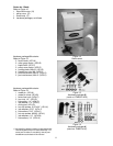
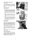
Setting Fence-to-Table Gap
The gap between the bottom of the rip fence
and the table top should be high enough that the
fence will not scrape along the table, yet low
enough that thin workpieces won’t slip beneath
it. The gap should be equal along the length of
the fence. Adjust as follows:
Refer to Figures 29 and 30.
1. Lock the fence assembly to the front rail by
pushing the fence handle down. The front
rail screws should still have “play” in them.
2. Lift up on both guide rail and fence together
until the fence/table gap at the front edge of
the table is acceptable.
Figure 26
Figure 27
Figure 28
Figure 29