


24
2. Loosen lock knob and raise or lo
w
er upper
blade guide assembly to approximately
3/16” above the material being cut.
3. Tighten lock knob.
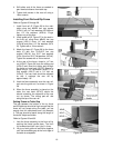
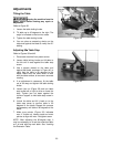
4. The guide post (Figure 46) is spring loaded.
To adjust the tension on the spring, unscrew
and completely remove knob, then tighten
or loosen set screw, until desired tension is
reached. Re-install knob.
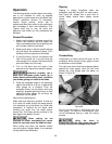
Upper Bearing Guides
Refer to Figures 47, 48, 49.
1. Disconnect machine from power source.
2. Blade must already be tensioned and
tracking properly.
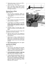
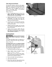
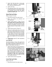
3. Loosen thumb screw (A, Figure 47) and
move guide block by turning knob (B) so
that the front of the guide wheels (C) are
just behind the gullet (curved area at base
of tooth) of the blade, as shown in Figure
48. This distance is usually about 0.016” (or
1/64”).
4. Tighten thumb screw (A, Figure 47).
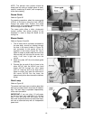
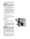
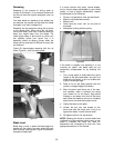
5. Loosen the socket screw (D) and turn the
screw (E) on each guide wheel to move the
guide wheels about 0.004” from the blade.
(A quick way to set this distance is to place
a crisp dollar bill, which is approximately
.004” thick, between guide wheel and blade,
and move the guide until it just contacts the
bill.)
6. Tighten socket screw (D) when adjustment
is satisfactory.
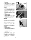
Thrust Bearing
The thrust bearing (F, Figure 49) supports the
back edge of the blade during operation, and is
set so that the blade will contact it only when the
blade is under pressure during a cut.
7. Loosen thumb screw (G, Figure 49) and turn
knob (H) to move the thrust bearing (F) in or
out until the bearing is approximately 0.016”
(or 1/64”) behind the blade. You can use a
feeler gauge to set this distance, or simply
place a crisp dollar bill folded twice (four
thicknesses) between the thrust bearing and
the blade. (A dollar bill is approximately
0.004” thick, so four thicknesses provides
the necessary distance.)
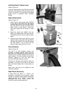
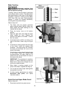
8. Tighten thumb screw (G, Figure 50).
Lower Bearing Guides
Refer to Figure 50.
1. Disconnect machine from power source.
Figure 47
Figure 48
Figure 49
Figure 50