


25
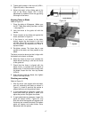
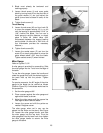
2. Blade must already be tensioned and
tracking properly.
3. Loosen thumb screw (J) and move guide
block by turning knob (K) so that the front of
the guide wheels (L) are just behind the
gullet (curved area at base of tooth) of the
blade.
4. Tighten thumb screw (J).
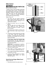
Thrust Bearing
5. Loosen thumb screw (M) and turn knob (N)
to move the support bearing (O) in or out
until the bearing is approximately 0.016” (or
1/64") behind the blade. You can use a
feeler gauge to set this distance, or simply
place a dollar bill folded twice (four
thicknesses) between the support bearing
and the blade. (A dollar bill is .004” thick, so
four thicknesses provides the necessary
distance.)
6. Tighten thumb screw (M).
7. Loosen the socket screw (P) and turn the
screw (R) on each guide wheel to move the
guide wheels about .004” from the blade.
Tighten socket screw (P) when finished.
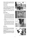
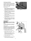
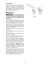
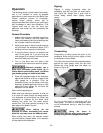
Miter Gauge
Refer to Figures 51, 52.
A miter gauge is provided for crosscutting. Slide
the miter gauge into the T-slot from the edge of
the table.
To use the miter gauge, loosen the handle and
rotate the gauge body until the desired angle on
the scale lines up with the pointer. Tighten
handle.
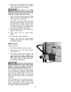
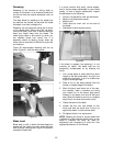
For precise crosscuts, the 90° angle of the miter
gauge to the blade can be verified as follows
(Refer to Figure 52). A wide blade works best for
this procedure.
1. Set the miter gauge at 90°.
2. Place a square against the miter gauge and
against the blade, as shown.
3. Adjust the miter gauge until the square lies
flush against both it and the blade.
4. Loosen the screw and shift the pointer as
needed. Retighten screw.
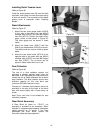
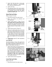
The miter gauge, when not in use, can be
placed into the hooks on the stand. See Figure
53. Loosen the miter gauge handle, and slide
the miter gauge into the top hook. Pivot the
miter gauge bar into the lower hook, then tighten
the miter gauge handle to secure the miter
gauge to the stand.
Figure 51
Figure 52
Figure 53