


14
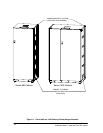
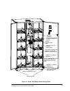
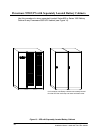
Po werware 9350 Series 685 and 1085 Auxiliary Battery Cabinets
Installation Manual 164201408 Rev. P00 053002
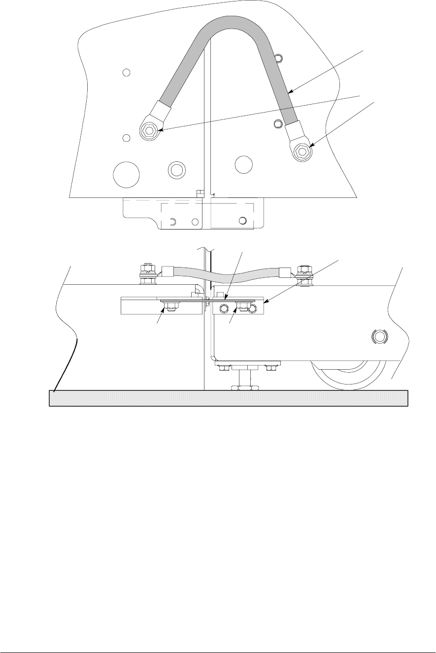
Nut from kit
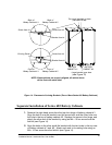
Front of 1085
Battery Cabinet
Bracket from kit
Front of
UPS
Nut from kit
Existing hinge
Ground Wire
Ground Stud
TOP VIEW
FRONT VIE W
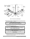
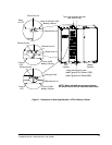
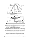
Figure 8. Attaching UPS Base to Series 1085 Base
12. Route the ground wire (from the field kit) from the customer ground stud in the
battery cabinet, under the lower right-hand battery tray, through the access
hole in the side panel of the UPS, and attach to customer ground stud in the
UPS cabinet. Hardware is provided on each ground stud.
13. Repeat Steps 2 through 12 to attach additional Series 1085 Battery Cabinets to
the other side of the first battery cabinet. Level the cabinets with the leveling
screws.
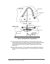
14. Locate the cabinet connecting bracket from the field kit. Attach the b racket to
the lower right-hand side of the Series 685 base using 2 M4 screws.
15. Locate the large flat bracket from the field kit. Place one end of the bracket
over the stud on the bottom side of the UPS cabinet lower right-hand hinge,
and the other end over the stud on the bottom side of the lower right-hand
hinge on the Series 685 Battery Cabinet (see Figure 9).
16. Attach the bracket to the hinges with two M8 self-locking nuts from the field kit.