


29
Po werware 9350 Series 685 and 1085 Auxiliary Battery Cabinets
Installation Manual 164201408 Rev. P00 053002
Connecting to
Powerware 9350 ---80 and 160
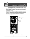
This chapter will explain how to electricall y connect your battery cabinets to
your Powerware 9350---80 or 160 UPS.
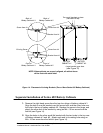
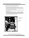
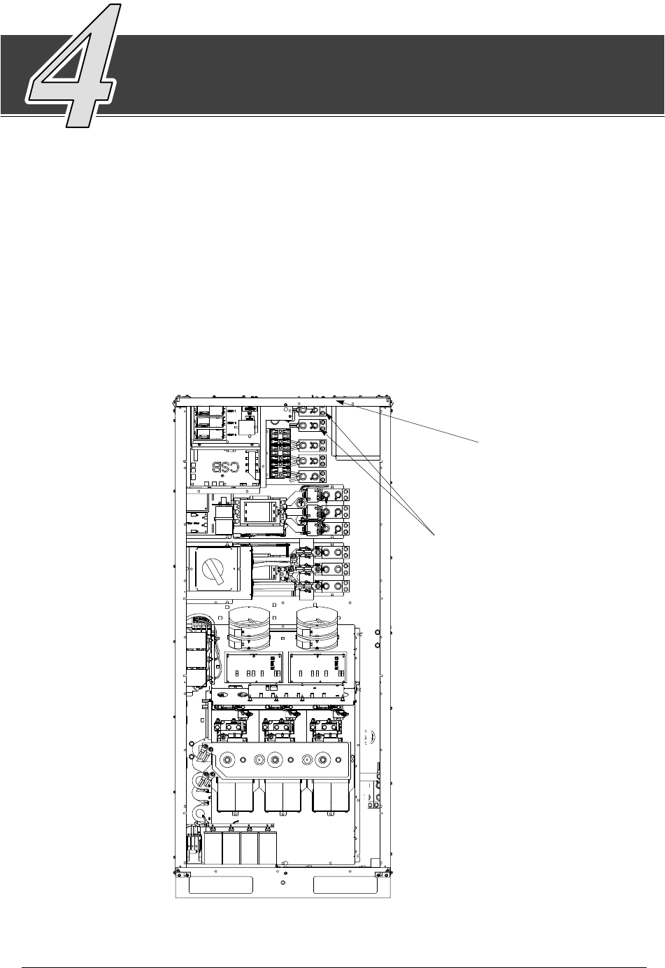
Figure 18 details the Battery cabinet DC connections and control wiring connection
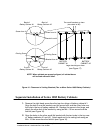
point in a P owerware 9350---80 UPS. Figure 19 details the same connections in a
Powerware 9350---160 UPS.
NOTE: See Table C in Appendix A for sizing wire for separate battery configurations.
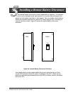
There are no battery cabinet-to-UPS mechanical attachment requirements for this
type of system. However, individual battery cabinets should be attached and
grounded to each other. Please refer to later sections of this chapter for
instructions on these procedures.
DC INPUT
from battery
to UPS
(E4, E5)
CUST TB terminal block
for control wiring.
Mounted toinside top of
cabinet.
Figure 18. Battery Connections for a Powerware 9350---80