


A --- 7
Po werware 9350 Series 685 and 1085 Auxiliary Battery Cabinets
Installation Manual 164201408 Rev. P00 053002
DESCRIPTION:
DRAWING NO:
2of2
SHEET:
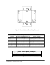
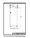
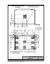
WALL --- NO BACK ACCESS REQUIRED
BOTTOM VIEW
914.4 (36.00)
MINIMUM CLEARANCE
FOR SUBASSEMBLY
REMOVAL
TOP VIEW
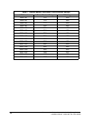
Dimensions are in millimeters (inches)
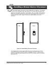
Series 685 Battery Cabinet
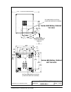
Series 685 Battery Cabinet
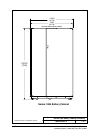
Series 685 Battery Cab inet (plan)
164201408--1
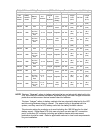
201.1
(7.92)
335
(13.19)
120
(4.72)
80
(3.15)
175
(6.89)
282
(11.1)
226.9
(8.93)
280.4
(11.04)
148
(5.83)
75
(2.95)
735.8
(28.97)
613
(24.14)
135
(5.32)
453
(17.83)
300.4
(11.83)
61.4
(2.42)
141.4
(5.57)
802.7
(31.6)
530
(20.87)
690
(27.17)
151
(5.95)
71
(2.80)
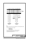
TOP CABLE ENTRY LOCATION
(COVER SECURED WITH SCREWS)
BOTTOM CABLE ENTRY LOCATION
(COVER SECURED WITH SCREWS)