


A --- 2
Po werware 9350 Series 685 and 1085 Auxiliary Battery Cabinets
Installation Manual 164201408 Rev. P00 053002
1. The output of the UPS is a separately derived source. Output neutral is bonded
to equipment ground through the main bonding jumper. Refer to NEC Article
250 and local codes for proper grounding practices.
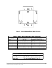
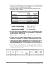
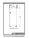
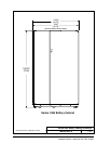
2. Your battery cabinet operating environment must meet the size and weight
requirements shown in Table A:
Table A. Equipment Weight and P oint Loading (on casters)
(4 leveling feet are provided)
Weight Point Loading
Component Kg(lb) Kg(lb)
Series 685-J14 869 (1915) 4 at 217 (479)
Series 685-J17 1111 (2450) 4 at 278 (613)
Series 1085-J27 1429 (3150) 8 at 179 (394)
Series 1085-J31 1588 (3500) 8 at 199 (438)
Series 1085-J37 1708 (3765) 8 at 214 (471)
Series 1085-J47 2178 (4800) 8 at 272 (600)
3. The basic environmental requirements for operation of the battery system are:
Ambient Temperature Range: 10 --- 40˚C (50 --- 10 4˚F)
Recommended Operating Range: 2 0 --- 25˚C (6 8 --- 77˚F)
Maximum Relative Humidity: 95% noncondensing
4. Use Class 1 wiring methods (as defined by the NEC) for control wiring. Install
the control wiring in separate conduit from the power wiring. The wire should
be rated at 24 volts, 1 amp minimum.
5. Battery voltage is computed at 2 volts per cell as defined by Article 480 of the
NEC. Rated battery current is computed at 1.8 volts per cell.
6. The battery wiring used between the battery and the UPS should not allow a
voltage drop of more than 1% of nominal DC voltage at rated battery current.
7. A battery disconnect switch is recommended, and may be required by NEC or
local codes when batteries are separately l ocated. The battery disconnect
switch may be supplied as an accessory, and should be installed between the
battery and the UPS.
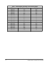
8. If the conductors used for DC input from the battery cabinet(s) to the UPS are
those provided by the UPS manufacturer, and the UPS and battery cabinet are
manufactured by the same supplier, then it is acceptable if they do not meet the
noted minimum conductor sizes.
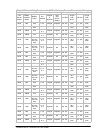
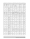
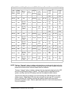
Table B. External Ground Wire Requirement s for Battery Cabinets
UPS
Model
Battery
Series
Battery
Type
#of
Cabinets
Integral
or
Separate
Battery
Wire Size
Battery
Tool Size
Battery
Cabinet
Torque
N-M
(lb-in)
all 685 or 1085 all all all 1/0 7/16I slot 5.6 (50)