


vi
Po werware 9350 Series 685 and 1085 Auxiliary Battery Cabinets
Installation Manual 164201408 Rev. P00 053002
dddddddddddddddddddddddddddddddddddddddddddddddddddddddddddddddddddddd
ddddddddddddddddddddddddddddddddddddddddddddddddddddddd
List of
Figures
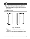
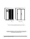
Figure 1. Typical Battery Cabinets 1.........................................
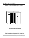
Figure 2. UPS with Lineup and Match Battery Cabinet 2........................
Figure 3. UPS with Separate Battery Cabinets (Attached to Each Other) 3........
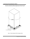
Figure 4. Cabinet as Shipped, with Outer Packaging and Pallet 6................
Figure 5. Removing F ront and Rear Supports 8...............................
Figure 6. UPS with Integral Battery Cabinet 11.................................
Figure 7. Placement of Attaching B rackets, UPS to Battery Cabinet 13............
Figure 8. Attaching UPS Base to Series 1085 Base 14..........................
Figure 9. Attaching UPS Base to Series 685 Base 15............................
Figure 10. Series 685 Battery Cabinet Wiring Detail 17..........................
Figure 11. Series 685 and 1085 Battery Cabinet Hanger Brackets 18..............
Figure 12. Series 1085 Battery Cabinet Wiring Detail 19.........................
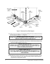
Figure 13. UPS with Separately Located Battery Cabinets 20.....................
Figure 14. Placement of Joining Brackets
(Two or More Series 685 Battery Cabinets) 21.........................
Figure 15. Connecting Two Series 685 Bases 22...............................
Figure 16. Placement of Joining Brackets
(Two or More Series 1085 Battery Cabinets) 23........................
Figure 17. Connecting Two Series 1085 Bases 24..............................
Figure 18. Battery Connections for a Powerware 9350---80 29....................
Figure 19. Battery Connections for a Powerware 9350---160 30...................
Figure 20. Remote Battery Disconnect Enclosure 33............................
Figure 21. Knockout Pattern for Remote Battery Disconnect 35...................