


30
Po werware 9350 Series 685 and 1085 Auxiliary Battery Cabinets
Installation Manual 164201408 Rev. P00 053002
Powerware 9350---80 or 160 with Separate Battery Cabinets
1. Make sure that the UPS is properly installed and secured.
2. Roll the battery cabinets to their permanent location.
3. Attach and connect the battery cabinets to each other (refer to “The
Powerware 9350 UPS with Separate Battery Cabinets” section of Chapter 3).
4. If necessary, remove the cosmetic covers and doors from the UPS. Save
covers, screws, and brackets for later reuse.
5. Each battery cabinet in your system will have to be individually connected to
terminals E4 and E5.
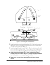
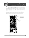
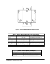
6. Route cables from positive (+) and negative (---) terminals in the bottom of
each battery cabinet through conduit (top or bottom entry) to terminals E4
and E5 of the UPS cabinet. See Figure 18 or 19 for location of terminals E4
and E5. Refer to Chapter 3, Figure 11 or Figure 13 for location of battery
cabinet positive (+) and negative (---) terminals.
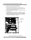
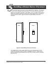
DC INPUT
from battery
to UPS
(E4, E5)
CUST TB terminal block
for control wiring.
Mounted toinside top of
cabinet.
Figure 19. Battery Connections for a Powerware 9350---160