


32
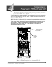
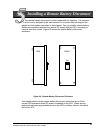
Po werware 9350 Series 685 and 1085 Auxiliary Battery Cabinets
Installation Manual 164201408 Rev. P00 053002
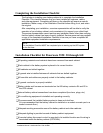
Installation Checklist for Powerware 9350---160
-All p acking materials and restraints have been removed from each cabinet.
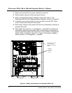
-Each cabinet in the battery system is placed in its correct location.
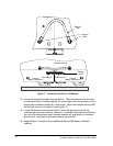
-All battery cabinets are bolted together.
-A ground wire is installed betw een all cabinets that are bolted together.
-All conduits and cables are properly routed to the battery cabinets.
-A g round conductor is properly installed.
-Battery cables and harness are terminated on the battery terminals E4 and E5 in the
UPS cabinet.
-Internal battery cabinet connections have been completed (bus bars, plugs, etc.)
-Air conditioning equipment is installed and operating correctly.
-The area around the installed battery system is clean and dust-free.
(It is recommended that the battery cabinet be installed on a sealed concrete pad or a
sealed concrete floor.)
-Adequate working area exists around the battery cabinet and other cabinets.
-Adequate lighting is provided around all battery cabinet equipment.
-A r emote battery disconnect control is mounted in its installed location and its wiring is
terminated inside the battery cabinet (OPTIONAL).