


2 – General Description
Chassis Controls
SN0051102-00 A 2-7
A
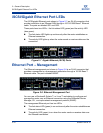
Heartbeat LED (Green)
The heartbeat LED blinks once a second as long the router firmware is
operational.
Input Power LED (Green)
The power LED shows the voltage status at the router logic circuit board. During
normal operation, this LED lights up to show that the router logic circuit board is
receiving the DC voltage from the power supply.
System Fault LED (Amber)
The system fault LED lights up to show that a fault exists in the router firmware or
hardware. Fault conditions include POST errors and over-temperature conditions.
The LED shows a blink code for POST errors and the over-temperature condition.
See Figure 2-4 and Tabl e 2- 1.
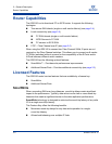
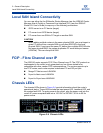
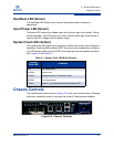
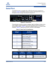
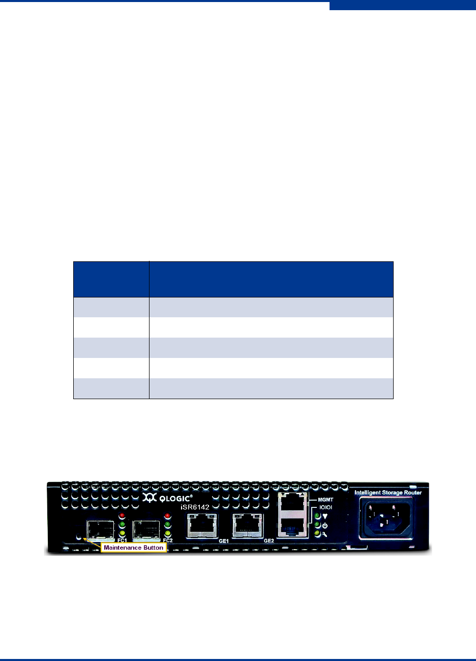
Chassis Controls
The maintenance button shown in Figure 2-5 is the only chassis control. Pressing
this button resets the router or recovers the router if it has become disabled.
Figure 2-5 Chassis Controls
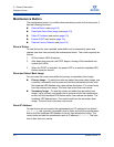
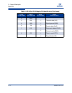
Table 2-1. System Fault LED Blink Patterns
System
Fault LED
Condition
OFF OK (operational)
3 Blinks System error
4 Blinks Management port IP address conflict
5 Blinks Over temperature
1 Blink Beacon - synchronized with the Heartbeat LED