


2 – General Description
Serial Port
SN0051102-00 A 2-13
A
Serial Port
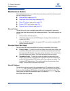
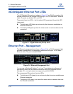
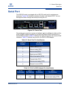
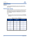
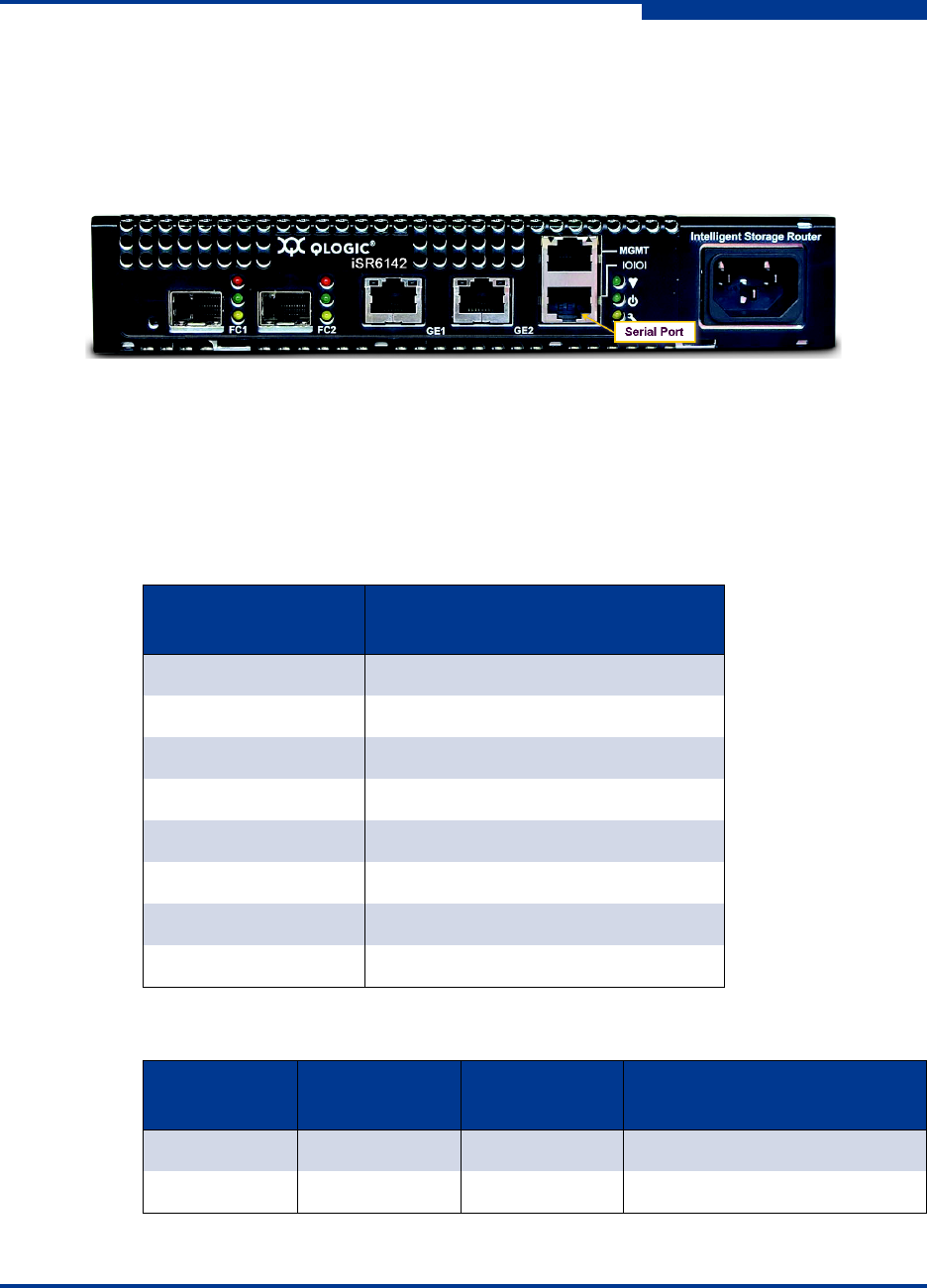
The iSR6142 router is equipped with an RS-232 serial port for maintenance
purposes. Figure 2-9 shows the serial port location. It is labeled IOIOI. You can
manage the router through the serial port using the CLI.
Figure 2-9 Serial Port
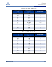
The serial port connection requires a standard, eight-wire Ethernet cable and the
RJ45-to-DB9F adapter (supplied) to convert the Ethernet RJ45 connector to a
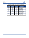
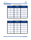
female DB9 connector. Tab le 2- 3 defines the serial port pins for the router’s RJ45
connector. Table 2-4 defines the pinout for the RJ45 to DB9 adapter.
Table 2-3. Serial Port Pin Identification
RJ45 Pin
Number
RJ-45 Pin
Description
1
Clear to send (CTS)
2
Data set ready (DSR)
3
Receive data (RxD)
4
Signal ground (GND)
5
Data carrier detect (DCD)
6
Transmit data (TxD)
7
Data terminal ready (DTR)
8
Request to send (RTS)
Table 2-4. RJ-45 to DB-9 Adapter Pin Identification
RJ-45
Pin Number
DB-9F
Pin Definition
DB-9
Pin Number
DB-9
Pin Definition
1 CTS 7
Request to send (RTS)
2DSR 4
Data terminal ready (DTR)