


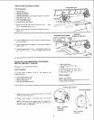
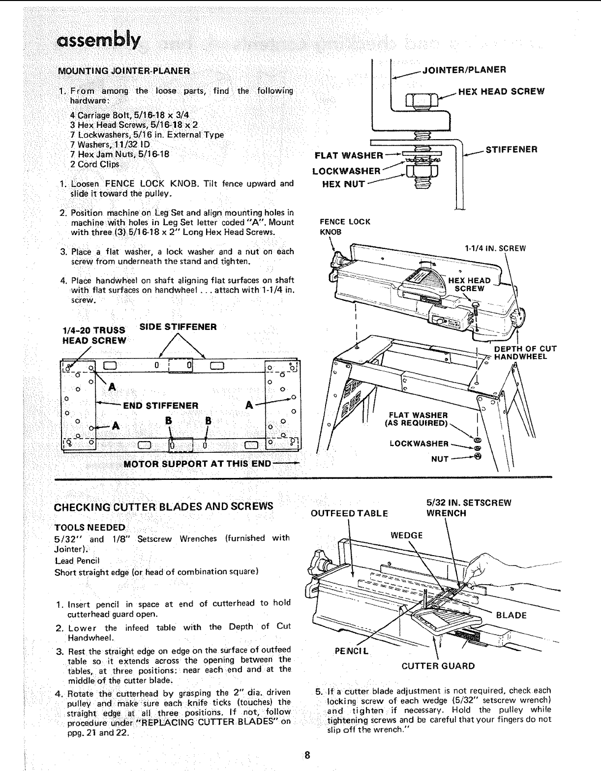
MOUNTING JOINTER:PLANER
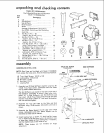
hardware:-
4 Carriage 8ott,: 5./16_18 x 3/41
3 Hex Head: screws,: 5/16_18 X:2
7 Lockwashers, 5/i6 in. EXternal Type
7 Washers, 11t32 1D
7 Hex Llam Nuts, 5/16-18
2 Cord Clips
the following
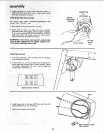
t. Loosen FENCE LOCK KNOB. Tilt fence upward and
slide it toward the pulley.
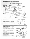
2. PoSition machine on Leg Set and align mounting holes in
machine with holes in Leg Set letter coded °'A'. Mount
with three (3) 5/1 6-18 x 2" Long Hex Head Screws.
3. Place a flat washer, a lock washer and a nut on each
screw from underneath the stand and tighten.
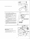
4. PlaCe handwheet on shaft aligning flat surfaces on shaft
with flat surfaces on handwheel.., attach with 1-1/4 in.
screw.
1/4-20 TRUSS SIDE STIFFENER
HEAD SCREW
HEXNUT W H
____ JO INTER/PLANER
HEAD SCREW
STIFFENER
FENCE LOCK
KNOB
,\
1-1/4 IN. SCREW
t
I
I
1
DEPTH OF CUT
HANDWHEEL
.,_MOTOR SUPPORT AT THIS END ----_
J
/
CHECK! NG CUTTER BLADES AND SCR EWS
TOOLS NEEDED
5/32" and 1/8" Setscrew Wrenches (furnished
Jointer),
Lead Pencil
Short straight edge (or head of combination square)
with
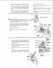
1. Insert pencil in space at end of cutterhead to hold
cutterhead guard open.
2. Lower the infeed table with the Depth of Cut
Handwheet.
3. Rest the straight edge on edge on the surface of outfeed
table so it extends across the opening between the
tables, at three positions: near each end and at the
middle of the cutter blade_
4. ROtate the cutterhead by grasping the 2" dia. driven
pulley and make-sure each knife ticks (touches) the
straight edge at all three positions. If not, follow
procedure under "REPLACING CUTTER BLADES" on
ppg. 21 and 22.
OUTFEED TABLE
PENCI L
WEDGE
5/32 IN. SETSCREW
WRENCH
CUTTER GUARD
5. If a cutter blade adjustment is not required, check each
locking: screw of each wedge (5/32" setscrew wrench)
and tighten if necessary. Hold the pulley while
tightening screws and be careful that your fingers do not
slip off the wrench."