


iNSTALLING SLIDING GUARD
PARTS NEEDED
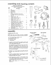
1 Sliding Guard
I Sliding Guard Knob
t Sliding Guard Rod
2 Sliding Guard Washers (one side of washer is concave)
1 Hex. Nut 1/2 in.* t3
1 Sl_it lockwasher 1/2 in.
2 E×t, tooth Iockwashers
2 10-32xl/4 Pan Hd. Screws
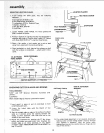
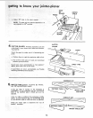
t. Screw nut alt the way onto long end of rod.. , place
1/2 in. lockwasher next to nut.
2. Screw rod all the way into Jointer with short end up...
tighten nut.
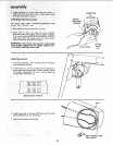
SLIDING GUARD
1/2 IN. HEX NUT
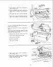
3, Attach sliding guard to fence with two machine screws
and lockwashers,
SLIDING GUARD KNOB
10-32xl/4 SCREWS
EXT. TOOTH
LOCKWASHERS
WASHE R
(CONCAVE SIDE UP)
4. Place one Sliding Guard Washer, concave side DOWN on
support rod.
5. Drop sliding guard onto rod.., place other washer, con-
cave side UP on rod , , . screw on Sliding Guard Knob,
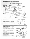
MOUNTING RECOMMENDED CRAFTSMAN
MOTOR AND BELT GUARDS
See page 5 for recommended motors.
PARTS NEEDED
4 carriage bolts, 5]16-18 x 3/4 in., flat washers, lock
washers and nuts.
1 Jointer Planer Belt Guard
1 Motor Pulley Belt Guard
1 Belt Guard Support
! Belt Guard Support Bracket
3 Belt Guard Clips
1 Motor Pulley, 2-t/2 in. dia.
1 V-Belt
2 Pan Head Screws 10 - 32 x t/2 in,
2 Hex, Hd. Screws 1/4 - 20 x 1/2 in.
2 Hex, Nuts 1/4- 20
TOOLS NEEDED
Medium Screwdriver
5/32 in. Setscrew Wrench (furnished with Jointer)
1/2 and 7/!6 in, Wrenches
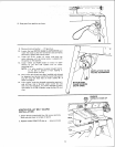
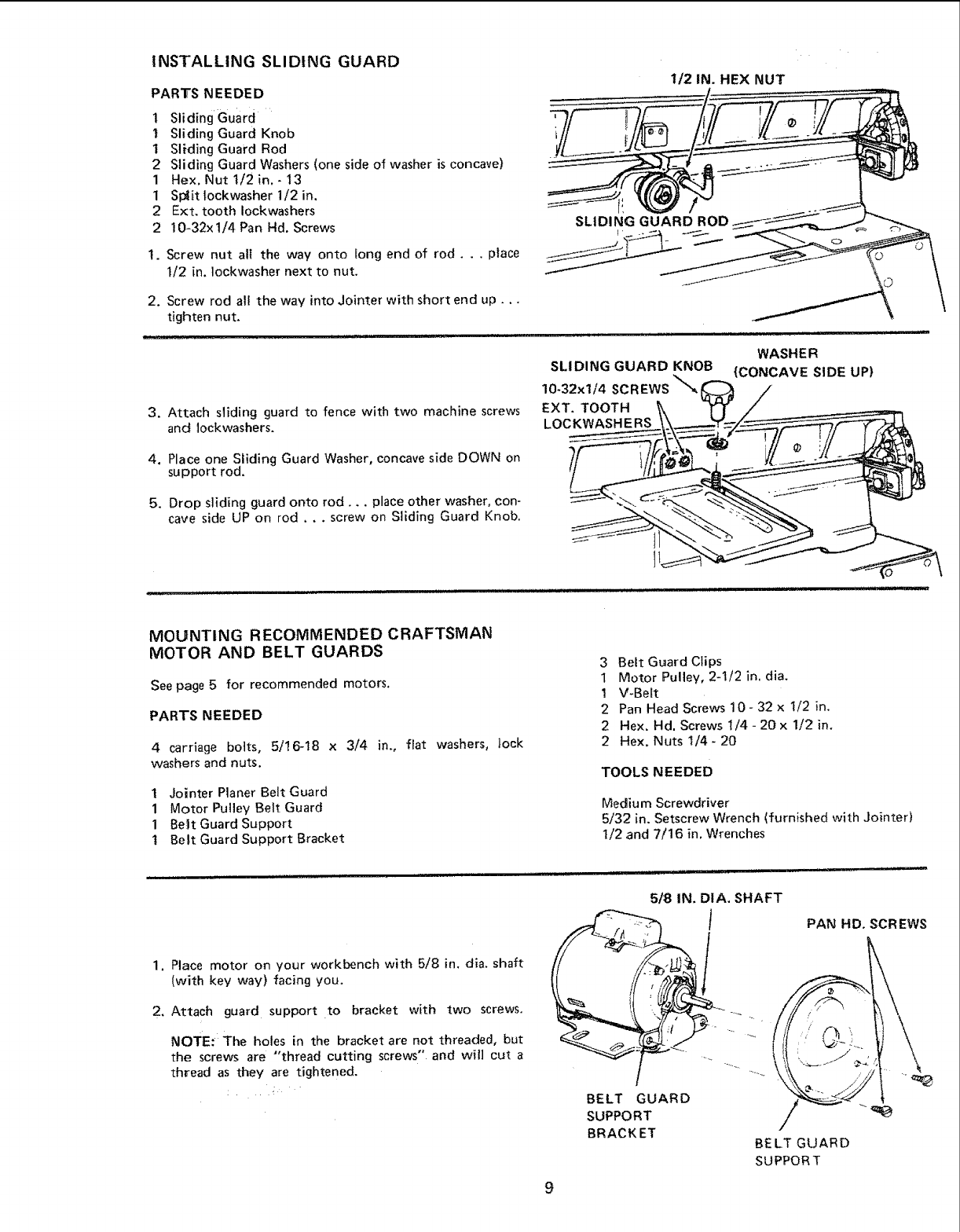
1, Place motor on your workbench with 5/8 in. dia, shaft
(with key way) facing you.
2. Attach guard support to bracket with two screws.
NOTE: The holes in the bracket are not threaded, but
the screws are "thread cutting screws" and win cut a
thread as they are tightened,
5/:8 IN. DIA, SHAFT
BELT GUARD
SUPPORT
BRACKET
PAN HD. SCREWS
BELT GUARD
SUPPORT
9