


operating controls
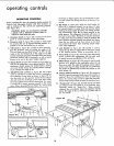
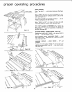
OPERATING CONTROLS
Before operating the saw, the operator should examine all
controls until thoroughly familiar with their functions, as
well as making sure that controls are operating properly.
(See figure 39.)
CAUTION: Under no circumstances should
a blade with a diameter greater than 12
inches be used with this saw.
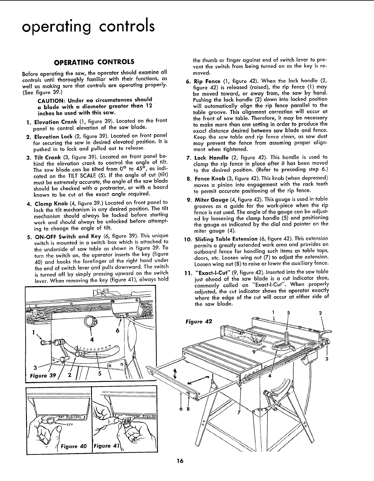
1. Elevation Crank (li figure 39i. Located on the front
panel to control elevation of the saw blade,
2. Elevation Lock (2, figure 39). Located on front panel
for securing the saw in desired elevated position. It is
pushed in to lock and pulled out to release.
3. Tilt Crank (3, figure 39). Located on front panel be-
hind the elevation crank to control the angle of tilt.
The saw blade can be tilted from 0° to 45 °, as indi-
cated on the TILT SCALE (5). If the angle of cut (tilt)
must be extremely accurate, the angle of the saw blade
should be checked wffh a protractor, or with a board
known to be cut at the exact angle required.
4. Clamp Knob (4, figure 39.) Located on front panel to
lock the tilt mechanism in any desired position. The tilt
mechanism should always be locked before starffng
work and should always be unlocked before attempt-
ing to change the angle of tilt.
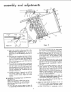
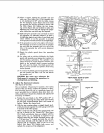
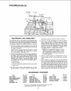
5. ON-OFF Switch and Key (6, figure 39). This unique
switch is mounted in a switch box which is attached to
the underside of saw table as shown in figure 39. To
turn the switch on, the operator inserts the key (figure
40) and hooks the forefinger of the right hand under
the end of switch lever and pulls downward. The switch
is turned off by simply pressing upward on the switch
lever. When removing the key (figure 41), always hold
1
\
4
3
Figure 39
the thumb or finger against end of switch lever to pre-
vent the switch from being turned on as the key is re-
moved.
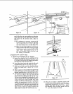
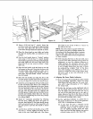
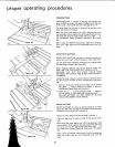
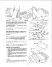
6. Rip Fence (1, figure 42). When the lock handle (2,
figure 42) is released (raised), the rip fence (1) may
be moved toward, or away from, the saw by hand.
Pushingthe lock handle (2) down into locked position
will automatically align the rip fence parallel to the
table groove. This alignment correction will occur at
the front of saw table. Therefore, it may be necessary
to make more than one setting in order to produce the
exacf distance desired between saw blade and fence.
Keep the saw table and rip fence clean, as saw dust
may prevent the fence from assuming proper align-
ment when tightened.
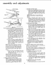
7. Lock Handle (2, figure 42). This handle is used to
clamp the rip fence in place after it has been moved
to the desired position. (Refer to preceding step 6.)
8. Fence Knob (3, figure 42). This knob (when depressed)
moves a pinion into engagement with the rack teeth
to permit accurate positioning of the rip fence.
9. Miter Gauge (4, figure 42). This gauge is used in table
grooves as a guide for the work-piece when the rip
fence is not used. The angle of the gauge can be adjust-
ed by loosening the clamp handle (5) and positioning
the gauge as indicated by the dial and pointer on the
miter gauge (4).
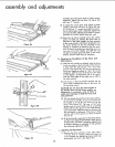
10. Sliding Table Extension (6, figure 42). This extension
permits a greatly extended work area and provides an
outboard fence for handling such items as table tops,
doors, etc. Loosen wing nut (7) to adjust the extension.
Loosen wing nut (8) to raise or lower the auxiliary fence.
11. "'Exact-I-Cut" (9, figure 42). Insertedintothe saw table
just ahead of the saw blade is a cut indicator shoe,
commonly called an "Exact-I-Cut". When properly
adjusted, the cut indicator shows the operator exactly
where the edge of the cut will occur at either s_de of
the saw blade.
2
Figure 42
-KEY
Figure 40 Figure 41
6 8
16