


J
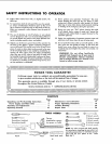
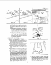
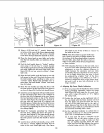
EXTENSION ROD
SUPPORTS
Figure 7
Figure 8
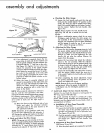
SMALL STEEL SCALE
TABLE EXTENSfON ,_
Figure 9
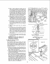
FENCE GUID_ BAR
RACK
SWITCH
BOX
SCREW
Figure 10
ii
(2)
(3)
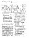
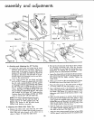
feners. (See figure 5.) Using parts from the correct
loose parts bag, assemble the legs to the saw base
with the sixteen 5/16-18x5/8 inch screws and
5/16-18 nuts. (See figure 6.) Leave these screws
loose in order to facilitate mounting the stiffeners.
All four leg stiffeners are identical and since the
distance on the sides is greater than the distance
on the ends, the leg stiffeners used on the sides
should be attached at outer holes while the
stiffeners at the ends should be attached at inner
holes. (See figure 6.)
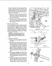
Assemble the four stiffeners with sixteen 1/4-
20 x 1/2 inch screws and 1/4-20 inch nuts. After
stiffeners are all in place, tighten all screws
securely. Install leveling feet, each with 2
1/2-13 x 3/4 x 5/16 hex nuts. (See figure 6.)
Place the saw in an upright position on its legs.
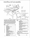
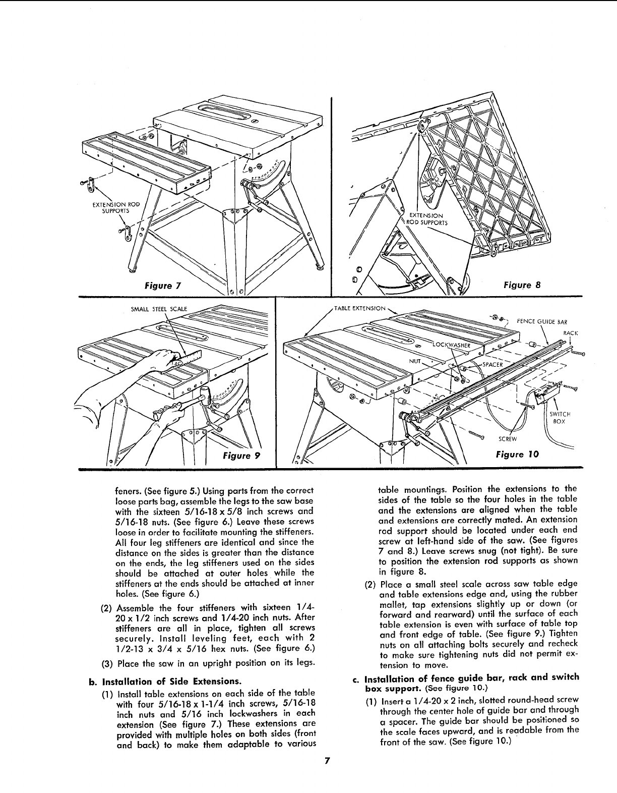
b. Installation of Side Extensions.
(1) Install table extensions on each side of the table
with four 5/16-18x 1-1/4 inch screws, 5/16-18
inch nuts and 5/16 inch Iockwashers in each
extension (See figure 7.) These extensions are
provided with multiple holes on both sides (front
and back) to make them adaptable to various
table mountings. Position the extensions to the
sides of the table so the four holes in the table
and the extensions are aligned when the table
and extensions are correctly mated. An extension
rod support should be located under each end
screw at left-hand side of the saw. (See figures
7 and 8.) Leave screws snug (not tight). Be sure
to position the extension rod supports as shown
in figure 8.
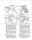
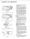
(2) Place a small steel scale across saw table edge
and table extensions edge and, using the rubber
mallet, tap extensions slightly up or down (or
forward and rearward) until the surface of each
table extension is even with surface of table top
and front edge of table. (See figure 9.) Tighten
nuts on all attaching bolts securely and recheck
to make sure tightening nuts did not permit ex-
tension to move.
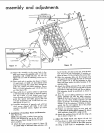
c. Installation of fence guide bar, rack and switch
box support. (See figure 10.)
(1) Inserta 1/4-20 x 2 inch,slotted round-head screw
through the center hole of guide bar and through
a spacer. The guide bar should be positioned so
the scale faces upward, and is readable from the
front of the saw. (See figure 10.)