


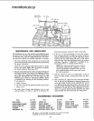
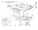
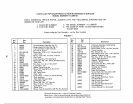
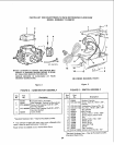
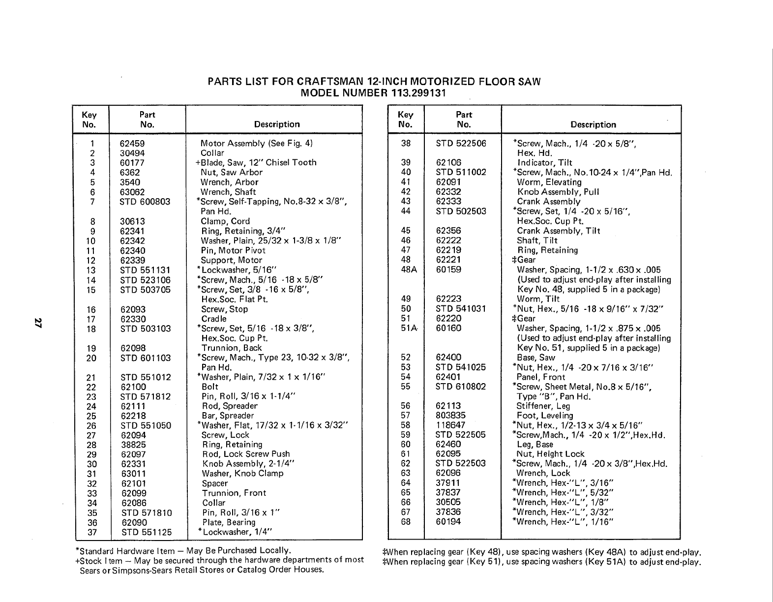
PARTS LIST FOR CRAFTSMAN 12-INCH MOTORIZED FLOOR SAW
MODEL NUMBER 113.299131
Key Part
No. No. Description
1
2
3
4
5
6
7
8
9
10
11
12
13
14
15
16
17
18
19
20
21
22
23
24
25
26
27
28
29
30
31
32
33
34
35
36
37
62459
30494
60177
6362
3540
63062
STD 600803
30613
62341
62342
62340
62339
STD 551131
STD 523106
STD 503705
62093
62330
STD 503103
62098
STD 601103
STD 551012
62100
STD 571812
62111
62218
STD 551050
62094
38825
62O97
62331
63011
62101
62099
62086
STD 571810
62090
STD 551125
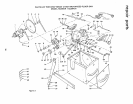
Motor Assembly (See Fig. 4)
Collar
+Blade, Saw, 12" Chisel Tooth
Nut, Saw Arbor
Wrench, Arbor
Wrench, Shaft
*Screw, Self-Tapping, No.8-32 x 3/8",
Pan Hd.
Clamp, Cord
Ring, Retaining, 3/4"
Washer, Plain, 25/32 x 1-3/8 x 1/8"
Pin, Motor Pivot
Support, Motor
* Lockwasher, 5/16"
*Screw, Mach., 5/16 -18 x 5/8"
*Screw, Set, 3/8 -16 x 5/8",
Hex.Soc. Flat Pt.
Screw, Stop
Cradle
*Screw, Set, 5/16 -18 x 3/8",
Hex.Soc. Cup Pt.
Trunnion, Back
*Screw, Mach., Type 23, 10-32 x 3/8",
Pan Hd.
*Washer, Plain, 7/32 x 1 x 1/16"
Bolt
Pin, Roll, 3/16 x 1-1/4"
Rod, Spreader
Bar, Spreader
*Washer, Flat, 17/32 x 1-1/16 x 3/32"
Screw, Lock
Ring, Retaining
Rod, Lock Screw Push
Knob Assembly, 2-1/4"
Washer, Knob Clamp
Spacer
Trunnion, Front
Collar
Pin, Roll, 3/16 x 1"
Plate, Bearing
* Lockwasher, 1/4"
*Standard Hardware Item - May Be Purchased Locally.
+Stock I tern - May be secured through the hardware departments of most
Sears or Simpsons-Sears Retail Stores or Catalog Order Houses.
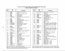
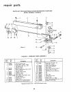
Key Part
No. No. Description
38 STD 522506
39 62106
40 STD 511002
41 62091
42 62332
43 62333
44 STD 502503
45 62356
46 62222
47 62219
48 62221
48A 60159
49 62223
50 STD 541031
51 62220
51A 60160
52 62400
53 STD 541025
54 62401
55 STD 610802
56
57
58
59
60
61
62
63
64
65
66
67
68
62113
803835
118647
STD 522505
62460
62095
STD 522503
62096
37911
37837
30505
37836
60194
*Screw, Mach., 1/4 -20 x 5/8",
Hex. Hd.
Ind icator, Tilt
*Screw, Mach., No.10-24 x 1/4",Pan Hd.
Worm, Elevating
Knob Assembly, Pull
Crank Assembly
*Screw, Set, 1/4 -20 x 5/16",
Hex.Soc. Cup Pt.
Crank Assembly, Tilt
Shaft, Tilt
Ring, Retaining
$Gear
Washer, Spacing, 1-1/2 x .630 x .005
(Used to adjust end-play after installing
Key No. 48, supplied 5 in a package)
Worm, Tilt
*Nut, Hex., 5/16 -18 x 9/16" x 7/32"
SGear
Washer, Spacing, 1-1/2 x .875 x .005
(Used to adjust end-play after installing
Key No. 51, supplied 5 in a package)
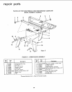
Base, Saw
*Nut, Hex., 1/4 -20x 7/16 x 3/16"
Panel, Front
*Screw, Sheet Metal, No.8 x 5/16",
Type "B", Pan Hd.
Stiffener, Leg
Foot, Level ing
*Nut, Hex., 1/2-13 x 3/4 x 5/16"
*Screw,Mach., 1/4 -20 x 1/2"',Hex.Hd.
Leg, Base
Nut, Height Lock
*Screw, Mach., 1/4 -20 x 3/8",Hex.Hd.
Wrench, Lock
*Wrench, Hex-"L", 3/16"
*Wrench, Hex-"L", 5/32"
*Wrench, Hex-"L", 1/8"
*Wrench, Hex-"L", 3/32"
*Wrench, Hex-"L", 1/16"
¢When replacing gear (Key 48), use spacing washers (Key 48A) to adjust end-play.
_4JVhenreplacing gear (Key 51), use spacing washers (Key 51A) to adju st end-play.