


-35-
W1770 21" Bandsaw w/Foot Brake
OPERATIONS
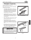
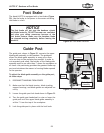
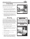
Foot Brake
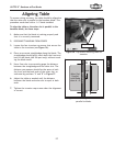
Figure 50. Foot brake location.
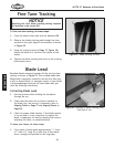
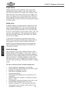
Guide Post
The guide post, shown in Figure 51, connects the upper
blade guide assembly to the bandsaw. The guidepost
allows the blade guide assembly to move up or down
to be as close to the workpiece as possible. In order to
cut accurately and safely, the bottom of the blade guide
assembly must be no more than 1" above the workpiece at
all times—this positioning provides the greatest blade sup-
port and minimizes the amount of moving blade exposed
to the operator.
To adjust the blade guide assembly on the guide post,
do these steps:
1. DISCONNECT BANDSAW FROM POWER!
2. Make sure that the blade tension, blade tracking,
support bearings, and blade guides are adjusted cor-
rectly.
3. Loosen the guide post lock knob shown in Figure 51.
4. Turn the guide post handwheel to raise or lower the
guide post until the upper blade guide assembly is
within 1" from the top of the workpiece.
5. Lock the guide post in place with the lock knob.
The Model W1770 is equipped with a foot brake (Figure
50). Use the brake to cut power to the motor and bring
the blade to a halt.
NOTICE
The foot brake will not stop the bandsaw wheels
and blade instantly. DO NOT become over confident
and relax your safety awareness because of the
foot brake feature. Make sure the bandsaw blade
has stopped moving completely before leaving the
machine.
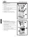
Figure 51. Guide post controls.
Guide Post
Handwheel
Guide Post
Lock Knob
Guide Post
Blade Guide
Assembly
Blade
Guard