


-57-
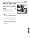
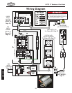
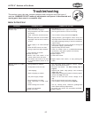
W1770 21" Bandsaw w/Foot Brake
SERVICE
PWR
ON
OFF
CONTROL PANEL
(viewed from behind)
A
AMP
RESET
96
1/2
T1/2 T3/6
NO14
3/4
T2/4
L1/1
L3/5
NO13
L2/3
5/6
95
18
22
26
NC15
SDE
NC16
MAG
SWITCH
ASSEMBLY
SDE MPE-18
L1
L1
L2
L2
Ground
Ground
Ground
Ground
220V
MOTOR
Ground
Hot
Hot
L6-30 PLUG
(as recommended)
220 VAC
LIMIT SWITCH (NC)
FOOT BRAKE
NC
SDE RA-30
18-26
SDE
MA-18
220V
POWER
SUPPLY
JUNCTION
BLOCK
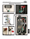
SHOCK HAZARD!
Disconnect power before servicing electrical
parts. Touching electrified parts will result in
severe burns, electrocution, or death.
21
1211
23 24
13
22
14
21
13
22
14
21
13
22
14
98
G
X
Y
CONTACTOR
THERMAL RELAY
Start
Capacitor
400MFD
250VAC
Run
Capacitor
45MFD
350VAC
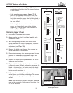
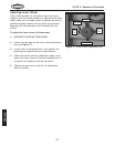
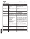
Troubleshooting
This section covers the most common problems and corrections with this type of
machine. WARNING! DO NOT make any adjustments until power is disconnected and
moving parts have come to a complete stop!
PROBLEM POSSIBLE CAUSE CORRECTIVE ACTION
Machine does not start or a
breaker trips.
1. Key is turned to "0".
2. Stop/reset button engaged.
3. Plug/receptacle is at fault or wired
incorrectly.
4. Motor connection wired incorrect-
ly.
5. Thermal protection circuit breaker
amperage is set too low or motor is
at fault.
6. Power supply is at fault/switched
OFF.
7. Motor ON/OFF switch is at fault.
8. Wiring is open/has high resistance.
9. Start capacitor is at fault.
10. Motor is at fault.
11. Wheel cover limit switch is not
closed, wheel covers are open.
12. Foot brake limit switch is at fault
or is pressed down (switch is not
closed).
1. Turn key to "1".
2. Rotate clockwise until it pops out/replace.
3. Test for good contact or correct the wiring.
4. Correct motor wiring connections (Page 56).
5. Unplug machine, open magnetic switch cover, turn
amperage dial on Thermal Protection Circuit Breaker
to a higher amperage setting. If switch is maxed out,
replace motor.
6. Ensure hot lines have correct voltage on all legs and
main power supply is switched ON.
7. Replace faulty ON/OFF switch.
8. Check for broken wires or corroded/disconnected
connections, and repair/replace as necessary.
9. Test/replace if faulty.
10. Repair/replace.
11. Close wheel covers.
12. Repair/replace limit switch, or stop pressing foot
brake.
Machine stalls or is under-
powered.
1. Wrong workpiece material.
2. Feed speed too fast for task.
3. V-belt slipping.
4. Blade is slipping on wheels.
5. Low power supply voltage.
6. Plug/receptacle is at fault.
7. Motor connection is wired incor-
rectly.
8. Motor bearings are at fault.
9. Motor has overheated.
10. Motor is at fault.
1. Use wood with correct moisture content, without
glues, and little pitch/resins.
1. Decrease feed speed. See Basic Cutting Tips on
Page 34.
3. Replace bad V-belt, align pulleys, and re-tension
(Page 47 & 48).
4. Adjust blade tracking and tension to factory specifi-
cations. See Page 17 or 22.
5. Ensure all hot lines have correct voltage on all
legs.
6. Test for good contacts and correct wiring.
7. Correct motor wiring connections (Page 56).
8. Test by rotating shaft; rotational grinding/loose
shaft requires bearing replacement.
9. Let motor cool, clean it off, and reduce workload.
10. Repair/replace.
Motor & Electrical