


35
Super Finish 7000
1
16
15
4
11
5
1
2
3
6
7
8
9
10
14
12
13
GB
descr IptIon of un It
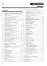
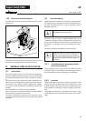
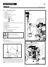
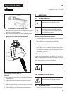
3.3 EXPLANATORY DIAGRAM
1 Tip guard with airless tip
2 Spray gun
3 High-pressure hose
4 Connection for high-pressure hose
5 Pressure gauge
6 Pressure control valve
7 Pressure relief valve
Symbols: Spraying
Circulation
8 ON / OFF switch
9 Indicating lamp (green indicates presence of line voltage)
10 Return hose
11 Suction hose
12 Inlet valve button
13 Outlet valve
14 Oil measuring stick under the oil screw plug
15 Inlet lter
16 Storage container for lter basket
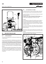
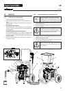
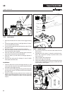
3.4 TRANSPORTATION
Device is very heavy (60 kg).
Only lift or carry the device in pairs.
Roll up the high-pressure hose and place over the carriage
frame.
Pull out the shaft.
Push or pull the device.
To retract the shaft, hold both buttons (1) pressed down.
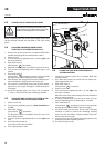
Transportation in vehicle
Secure the unit in the vehicle by means of suitable fasteners.
The device can be placed on its side if necessary. In this case,
please ensure that no attachments can be damaged. Atten-
tion: Paint or solvent residues can escape from the connec-
tions!