


49
Super Finish 7000
21
20
22
23
24
25
26
27
28
29
1
31
30
2
3
4
5
6
9
7
8
10
11
32
35
34
37
36
36
33
12
13
14
15
16
17
18
19
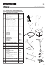
GB
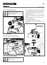
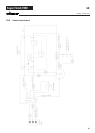
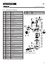
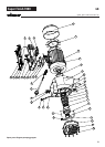
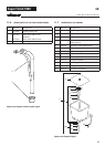
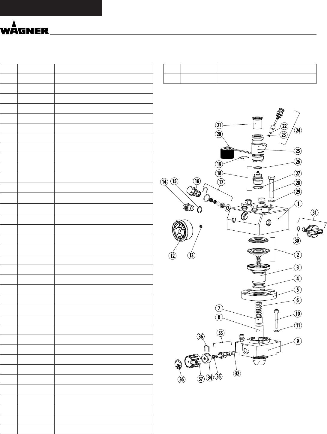
11.2 SPARE PARTS LIST PUMP HEAD
Item order- no des IgnatIon
1 0254 347 Paint head
2 0254 232 Diaphragm assy.
3 0341 314 Screw ange
4 9971 469 O-ring 35x2 (PTFE)
5 0341 315 Flange ring
6 0034 357 Pressure spring
7 0254 341 Insert, piston
8 0254 340 Piston D26
9 0254 230 Pressure insert assy.
10 9900 377 Cylinder head screw M8x 50 (4)
11 9920 102 Washer 8,4 (4)
12 9991 797 Manometer
13 9970 109 Sealing ring
14 0047 432 Double socket 1/4“ NPS/M16x1,5
15 9970 103 Sealing ring
16 0341 325 Valve guide
17 0341 702 Outlet valve, service set
18 0254 524 Inlet valve
19 0341 336 Clasp
20 9990 865 Dust protective cap
21 0340 339 Inlet
22 9971 486 O-ring 4x2 (FFPM)
23 0341 316 Wiper
24 0341 241 Inlet valve button
25 0252 279 Trigger housing
26 0341 331 Sealing ring
27 0341 330 Sealing ring
28 9900 217 Hexagon head screw M12x60 (6)
29 9920 204 Washer 13 (6)
30 9971 395 O-ring 10x1,25
31 0169 248 Relief valve (item. 30,31)
32 9971 365 O-ring 9,25x1,78
33 0252 294 Control valve assy. (item. 32,33)*
34 0010 859 Stop sleeve*
35 0010 861 Pressure spring*
36 0010 858 Clasp*
37 0341 219 Pressure regulating knob*
38 0341 599 Label
* When these parts are replaced the operating pressure has to
be set again by the customer service.
Spare parts diagram pump head
s pare par ts and accessor Ies