


44
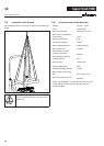
Super Finish 7000
2
3
14
GB
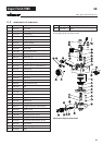
r epa Irs at the unIt
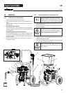
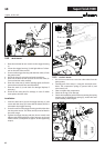
Before mounting the new diaphragm, clean the insert as well
as the grooved surface at the pressure insert (2) and the paint
section (3) and wipe o any oil.
Mounting is carried out in the reverse order.
1. First tighten all the hexagonal bolts (1) crosswise with
30Nm, then crosswise with 70Nm.
2. Before starting up leave the pressure control valve in the
open position for about 2 minutes while the motor is run-
ning (bleeds the unit). Only then close it until the noise of
the inlet valve can be heard.
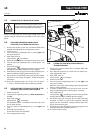
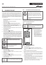
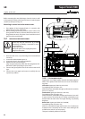
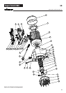
10.7 REPLACING THE POWER CABLE
These may only be carried out by a skilled
electrician. No liability is assumed for incor-
rect installation.
Switch the unit o.
Before all repair work: Unplug the power
plug from the outlet.
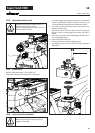
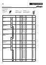
10.8 TYPICAL WEAR PARTS
Despite the use of high-quality materials the highly abrasive
eect of the paints means that wear can occur at the follow-
ing parts:
Inlet valve (spare part Order No.: 0254 524)
For replacing refer to Section 10.2
(failure becomes noticeable through performance loss and/or
poor or no suction)
Outlet valve (spare part Order No.: 0341702)
For replacing refer to Section 10.3
(failure becomes noticeable through performance loss and/
or poor suction) The outlet valve is usually considerably more
durable than the inlet valve. Thorough cleaning may already
help here.
Relief valve (spare part Order No.: 0169248)
For replacing refer to Section 10.5
(failure is noticeable through performance loss. Furthermore
material arrives constantly at the return hose although the
multifunction switch is set to spraying.
This part is relatively seldom a wear part.
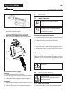
1. Dismount the cover (1) by loosening the 6 recessed-head
screws (4).
2. Loosen the cable threaded joint (2).
3. Loosen the wires in the mains terminal (3) .
4. Replace the unit connecting line.
(only an approved power cable with the designation H07-
RNF with a splash-proof plug may be used).
5. Connect the green/yellow wire to the contact with the PE
sign.
6. Connect the cover again and mount it carefully (do not
squeeze any cables!)