Owner Service 15
MAN0155 (Rev. 2/16/2007)
ADJUSTING SLIP CLUTCH
The slip clutch is designed to slip so that the gearbox
and driveline are protected if the cutter strikes an
obstruction.
A new slip clutch or one that has been in storage over
the winter may seize. Before operating the grinder,
make sure it will slip by performing the following opera-
tion:
1. Turn off tractor engine and remove key.
2. Remove driveline from tractor PTO.
3. Loosen eight 10 mm cap screws (23) to remove all
tension from pressure plate (22).
4. Hold clutch support (19) solid and turn shaft to
make sure clutch slips.
5. If clutch does not slip freely, disassemble and clean
the inner clutch plate faces (21), flange yoke (17),
and clutch support (19).
6. Reassemble clutch.
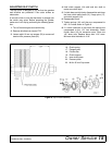
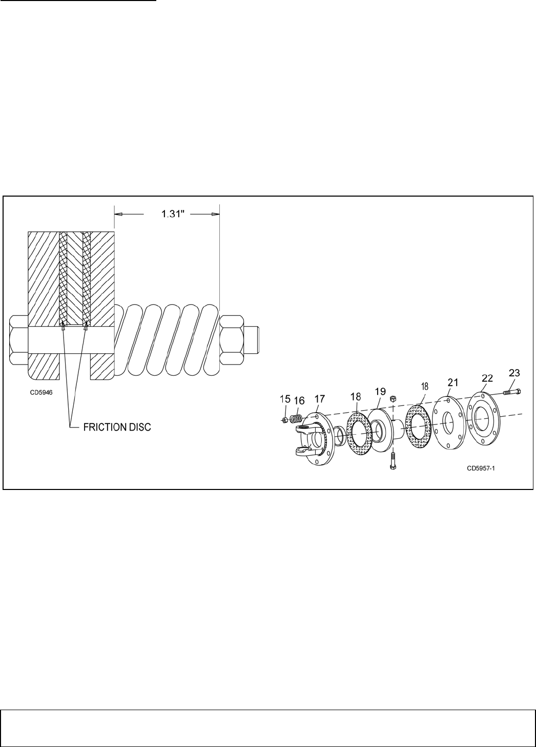
7. Tighten springs (16) until they are compressed to
the 1.31 inches shown in Figure 9.
8. If a clutch continues to slip when the springs are
compressed to the 1.31 inch dimension, check
friction discs (18) for excessive wear. Discs are
1/8" when new. Replace discs after 1/16" wear.
Minimum disc thickness is 1/16".
Figure 9. Slip Clutch Assembly
15. Nut
16. Clutch spring
17. Flanged yoke
18. Friction disc
19. Clutch support
21. Inner clutch plate
22. Pressure plate
23. M10 x 85 mm Cap screw


